
Page 288 - Low Temperature Energy Systems with Applications of Renewable Energy
P. 288
274 Low-Temperature Energy Systems with Applications of Renewable Energy
7.3 Energy-saving systems for biogas-producing plants
A modern biogas plant (BGP) is a complex of devices connected to each other by hy-
draulic, mechanical, electrical, and information communications. With high technol-
ogy, biogas production management should be as computer-assisted and automated
as possible in order to maximize efficiency. It is possible to achieve high productivity
of the BGP with an integrated combination of all innovative solutions. Schematic flow
diagrams for energy-saving systems for the production of biogas are shown in
Fig. 7.14 (with a recuperative heat exchanger 13) and in Fig. 7.15 (with a heat
pump 13), which ensure a reduction in energy costs for the production of biogas.
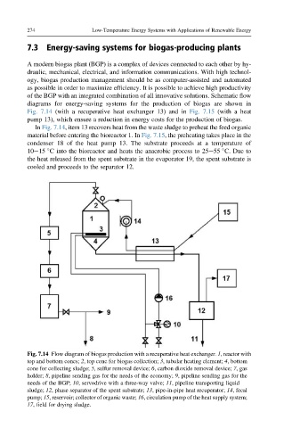
In Fig. 7.14, item 13 recovers heat from the waste sludge to preheat the feed organic
material before entering the bioreactor 1. In Fig. 7.15, the preheating takes place in the
condenser 18 of the heat pump 13. The substrate proceeds at a temperature of
10e15 C into the bioreactor and heats the anaerobic process to 25e55 C. Due to
the heat released from the spent substrate in the evaporator 19, the spent substrate is
cooled and proceeds to the separator 12.
Fig. 7.14 Flow diagram of biogas production with a recuperative heat exchanger. 1, reactor with
top and bottom cones; 2, top cone for biogas collection; 3, tubular heating element; 4, bottom
cone for collecting sludge; 5, sulfur removal device; 6, carbon dioxide removal device; 7, gas
holder; 8, pipeline sending gas for the needs of the economy; 9, pipeline sending gas for the
needs of the BGP; 10, servodrive with a three-way valve; 11, pipeline transporting liquid
sludge; 12, phase separator of the spent substrate; 13, pipe-in-pipe heat recuperator; 14, fecal
pump; 15, reservoir; collector of organic waste; 16, circulation pump of the heat supply system;
17, field for drying sludge.