
Page 35 - Low Temperature Energy Systems with Applications of Renewable Energy
P. 35
24 Low-Temperature Energy Systems with Applications of Renewable Energy
With reference to the heat pump in Fig. 1.6, the following exergy transfers take
place: The motor delivers exergy to the compressor which in turn imparts exergy to
the working fluid; the working fluid imparts exergy to the heat transfer fluid in the
condenser; the working fluid loses exergy via the throttling process; and the working
fluid receives exergy from the heat source in the evaporator. The difference between
the sum of the input exergy terms and the discharge exergy terms is the exergy loss
for each component, as shown below.
_
_
Compressor : DE C ¼ W C þ _ me 2 _ me 3 (1.20)
_
_
Condenser : DE CN ¼ _ me 3 E Q CN _ me 4 (1.21)
_
Throttle : DE TH ¼ _ me 4 _ me 1 (1.22)
_
_
Evaporator : DE EV ¼ _ me 1 þ E Q EV _ me 2 (1.23)
_
_
_
_
_
Heat pump : DE HP ¼ X DE i ¼W C þ E Q EV E Q CN (1.24)
i
Example 3 e Exergy analysis of basic vapor-compression
heat pump
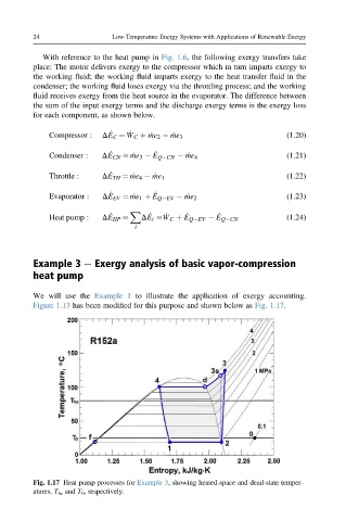
We will use the Example 1 to illustrate the application of exergy accounting.
Figure 1.13 has been modified for this purpose and shown below as Fig. 1.17.
Fig. 1.17 Heat pump processes for Example 3, showing heated-space and dead-state temper-
atures, T hs and T 0 , respectively.