
Page 84 - Low Temperature Energy Systems with Applications of Renewable Energy
P. 84
Characteristics of low-temperature energy sources for heat pumps 73
2.6.2.1 Ambient air as heat source
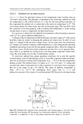
Figure 2.17 shows the principal scheme of low-temperature water heating using an
“air-water” heat pump. The principle of operation is the following: ambient air with
the temperature t 0 and volume fan loss V a is fed into the heat pump evaporator. In
the evaporator the ambient air is cooled and at the outlet its temperature is t out . The
a
room being heated has heat losses into the environment Q RH . The heat flow from
the condenser of the heat pump Q c with a working fluid temperature t c at the heating
system outlet is used to compensate for these heat losses.
It is necessary to determine the optimal air temperature at the heat pump evaporator
outlet t out for a given ambient temperature t 0 .
a
A change in the air temperature at the heat pump evaporator output t a out with a given
heat flow value Q c results in changing the ambient air volume loss Va which in turn
leads to a change in the fan drive energy losses. At the same time, the temperature
t out changes (at constant condenser outlet temperature t c ), thus changing the operating
a
conditions and energy losses for the heat pump compressor drive. Since the changes in
the energy losses for the heat pump compressor and fan drive are in opposite direc-
tions, there is an optimal air cooling level in the heat pump evaporator which mini-
mizes the total energy loss for the overall heating system.
To determine optimal heat pump operating conditions, let us plot the specific
external energy losses for the heating system l h versus the evaporator outlet air temper-
ature for an assumed working fluid temperature of t c ¼ 45 C in the low-temperature
hc
heating system. The defined factor A is taken as A ¼ 0.1; 0.5; and 1 C, taking into
account real values of pressure loss in the evaporator (a convective heat exchanger)
that are in the range of Dp ¼ 10e100 Pa. The range of ambient temperature is
from 20 Cto þ15 C. By substituting these values into Eq. (2.16) and
taking into account of the values of a real heat pump COP that can be estimated using
Fig. 2.17 Schematic flow diagram of low-temperature water heating using an “air-water” heat
pump: RH,room heating; HP, heat pump; C HP , heat pump condenser; EV HP , heat pump
evaporator; C, compressor; V, fan; L c , heat pump compressor drive input; L v , fan driver.