
Page 80 - Low Temperature Energy Systems with Applications of Renewable Energy
P. 80
Characteristics of low-temperature energy sources for heat pumps 69
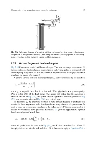
Fig. 2.16 Schematic diagram of a vertical soil heat exchanger in a heat pump: 1, heat pump
compressor; 2, heat pump evaporator; 3, heat pump condenser; 4, heating system; 5, circulating
pump; 6, heating system pump; 7, vertical soil heat exchanger.
2.5.2 Vertical in-ground heat exchangers
Fig. 2.16 illustrates a vertical soil heat exchanger. This heat exchanger represents a U-
tube polyethylene heat exchanger inserted into a well. The pipeline is connected with
the heat pump evaporator via a closed common loop in which a water glycol solution
circulates by means of a pump 5.
A general vertical soil heat exchanger length L v can be estimated by the equation:
3
10 Q HP 4 1
L v ¼ (2.6)
q w 4
where q w is a specific heat flow for a 1 m well, W/m; Q HP is the heat pump capacity,
kW; 4 is the COP of the heat pump. The reader will notice that this equation is
identical in form to Eq. (2.3), except that they are applied to different geometries: Eq.
(2.3) to a horizontal pipe and Eq. (2.6) to a vertical pipe.
To determine q w by analytical methods is very difficult because of unsteady heat
transfer in inhomogeneous soils that depends on many site-specific parameters. In
such a case, for preliminary calculations the value q w ¼ 50 W/m is assumed, but it
should be determined more precisely. Reference [5] gives an approximate equation
based on analyses of actual data:
w c
q w ¼ Kð1:4l 0:5Þ þ 1 ðt s t c Þ; (2.7)
w w
where all symbols are the same as in Eq. (2.4), and K takes the value K ¼ 1 if one U-
tube pipe is inserted into the well and K ¼ 1.28 if there are two pipes. Equation (2.6) is