
Page 75 - Low Temperature Energy Systems with Applications of Renewable Energy
P. 75
64 Low-Temperature Energy Systems with Applications of Renewable Energy
Fig. 2.13 Schematic flow diagram of a heat pump that operates with technological equipment
waste heat: 1, equipment requiring cooling (e.g., an air compressor); 2, water cooling tower; 3,
circulating pump of water cooling loop; 4, intermediate tankage; 5, cooling tower pump; 6,
heat pump evaporator pump; 7,8 and 9, heat pump evaporator, compressor and condenser,
respectively; 10, circulating condenser pump; 11, heat supply system.
going into the supply system by means of a circulating pump 10. At the same time the
cooling tower loading is reduced and in some cases it may be completely switched off;
then the technological heat will be completely used.
As a result of the wide use of refrigerators both in domestic life and industries, there
appear new possibilities for recycling heat energy, additional pumps being not always
necessary because technologically a refrigerator has all the elements of a heat pump.
Some manufacturers provide air and water condensers installed in series for off-the-
shelf refrigerators that makes it possible to use some part of waste heat for hot water
supply while serving the normal cooling needs inside the refrigerator. The scheme of
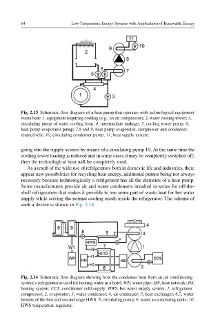
such a device is shown in Fig. 2.14.
Fig. 2.14 Schematic flow diagram showing how the condenser heat from an air conditioning
system’s refrigerator is used for heating water in a hotel: WP, water pipe; HN, heat network; HS,
heating system; CCS, conditioner cold supply; HWS, hot water supply system; 1, refrigerator
compressor; 2, evaporator; 3, water condenser; 4, air condenser; 5, heat exchanger; 6,7, water
heaters of the first and second stage HWS; 8, circulating pump; 9, water accumulating tanks; 10,
HWS temperature regulator.