
Page 71 - Low Temperature Energy Systems with Applications of Renewable Energy
P. 71
60 Low-Temperature Energy Systems with Applications of Renewable Energy
and nuclear power stations (NPSs), as well as large heat losses in (2) the heat distribu-
tion piping network [8].
The first loss (1) greatly influences environmental thermal pollution which may
contribute to global climate change. If energy consumption increases, this effect
may lead to a dangerous situation in the near future according to experts [8]. The
use of heat pumps that take advantage of power plant waste heat can mitigate this prob-
lem. In traditional heat supply systems, an amount of primary fuel is used to generate
the required amount of energy for the heating needs. In heat pumps a considerable part
of the useful thermal energy, 70e80%, is produced by low potential environmental
thermal energy.
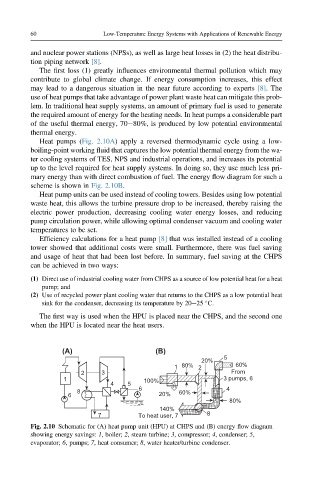
Heat pumps (Fig. 2.10A) apply a reversed thermodynamic cycle using a low-
boiling-point working fluid that captures the low potential thermal energy from the wa-
ter cooling systems of TES, NPS and industrial operations, and increases its potential
up to the level required for heat supply systems. In doing so, they use much less pri-
mary energy than with direct combustion of fuel. The energy flow diagram for such a
scheme is shown in Fig. 2.10B.
Heat pump units can be used instead of cooling towers. Besides using low potential
waste heat, this allows the turbine pressure drop to be increased, thereby raising the
electric power production, decreasing cooling water energy losses, and reducing
pump circulation power, while allowing optimal condenser vacuum and cooling water
temperatures to be set.
Efficiency calculations for a heat pump [8] that was installed instead of a cooling
tower showed that additional costs were small. Furthermore, there was fuel saving
and usage of heat that had been lost before. In summary, fuel saving at the CHPS
can be achieved in two ways:
(1) Direct use of industrial cooling water from CHPS as a source of low potential heat for a heat
pump; and
(2) Use of recycled power plant cooling water that returns to the CHPS as a low potential heat
sink for the condenser, decreasing its temperature by 20e25 C.
The first way is used when the HPU is placed near the CHPS, and the second one
when the HPU is located near the heat users.
(A) (B)
5
20%
1 80% 2 60%
2 3 From
1 100% 3 pumps, 6
4 5
6 4
8 60%
6 20%
80%
140%
7 To heat user, 7 8
Fig. 2.10 Schematic for (A) heat pump unit (HPU) at CHPS and (B) energy flow diagram
showing energy savings: 1, boiler; 2, steam turbine; 3, compressor; 4, condenser; 5,
evaporator; 6, pumps; 7, heat consumer; 8, water heater/turbine condenser.