
Page 72 - Low Temperature Energy Systems with Applications of Renewable Energy
P. 72
Characteristics of low-temperature energy sources for heat pumps 61
2.4.2 Recycled district heating water using extraction steam
from thermal power stations
One of the ways of improving a heating system is to use combined systems that include
central power station extraction steam (CPSES) and heat pump stations which use that
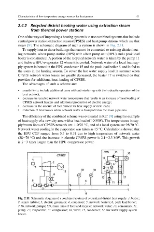
steam [9]. The schematic diagram of such a system is shown in Fig. 2.11.
To supply heat to those buildings that cannot be connected to existing district heat-
ing networks, a heat pump station (HPS) with a heat pump unit (HPU) and a peak load
boiler is constructed. A portion of the recycled network water is taken by the pump 11
and fed to a HPU evaporator 12 where it is cooled. Network water of a local heat sup-
ply system is heated in the HPU condenser 15 and the peak load boiler 6, and is fed to
the users in the heating season. To cover the hot water supply load in summer when
CPSES network water losses are greatly decreased, the heater 17 is switched on that
provides for additional heat loading of CPSES.
The advantages of such a scheme are:
• possibility to include additional users without interfering with the hydraulic operation of the
heat network;
• decrease in recycled network water temperature that results in an increase of heat loading of
CPSES network heaters and additional production of electric energy;
• decrease in the amount of fuel burned for heat supply of new loads;
• reduction of heat losses when network water is transported in the main pipelines.
The efficiency of the combined scheme was evaluated in Ref. [9] using the example
of heat supply of a new city area with a heat load of 10 MWt. The temperatures in sup-
ply/return lines of CPSES network are 110/70 C, and of a local system are 95/70 C.
Network water cooling in the evaporator was taken as 15 C. Calculations showed that
the HPU COP ranged from 5.5 to 8.31 due to high temperature of network water
(38e70 C) and the increase in electric CPSES power is 2.1e2.3 MW. This growth
is 2e3 times larger than the HPU compressor power.
Fig. 2.11 Schematic diagram of a combined system of centralized district heat supply: 1, boiler;
2, steam turbine; 3, electric generator; 4, condenser; 5, network heaters; 6, peak load boiler;
7,16, network pumps; 8,9, main lines of feed and recycled network water; 10, consumers; 11,
pump; 12, evaporator; 13, compressor; 14, valve; 15, condenser; 17, hot water supply system
heater.