Page 115 - MATLAB an introduction with applications
P. 115

100 ———  MATLAB: An Introduction with Applications

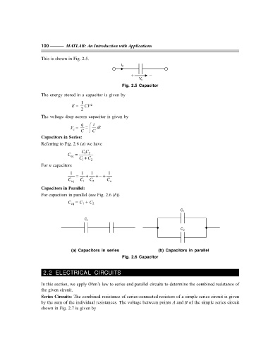
                   This is shown in Fig. 2.5.

                                                      i C
                                                          +       –
                                                              V c
                                                      Fig. 2.5 Capacitor
                   The energy stored in a capacitor is given by
                                    1
                                 E =   CV 2
                                    2
                   The voltage drop across capacitor is given by
                                    q   ⌠  i
                                V c  =   =    dt
                                    C    ⌡  C
                   Capacitors in Series:
                   Referring to Fig. 2.6 (a) we have
                                     CC
                               C  =   12
                                eq
                                    C 1  + C 2
                   For n capacitors
                                1  =  1  +  1  + ... +  1
                               C eq  C 1  C 2   C n

                   Capacitors in Parallel:
                   For capacitors in parallel (see Fig. 2.6 (b))
                               C eq  = C 1  + C 2
                                                                                C 1

                                      C 1

                                                                                C 2


                                (a) Capacitors in series                      (b) Capacitors in parallel
                                                      Fig. 2.6 Capacitor


                    2.2 ELECTRICAL CIRCUITS

                   In this section, we apply Ohm’s law to series and parallel circuits to determine the combined resistance of
                   the given circuit.
                   Series Circuits: The combined resistance of series-connected resistors of a simple series circuit is given
                   by the sum of the individual resistances. The voltage between points A and B of the simple series circuit
                   shown in Fig. 2.7 is given by


                   F:\Final Book\Sanjay\IIIrd Printout\Dt. 10-03-09
   110   111   112   113   114   115   116   117   118   119   120