
Page 118 - MATLAB an introduction with applications
P. 118
Electrical Circuits ——— 103
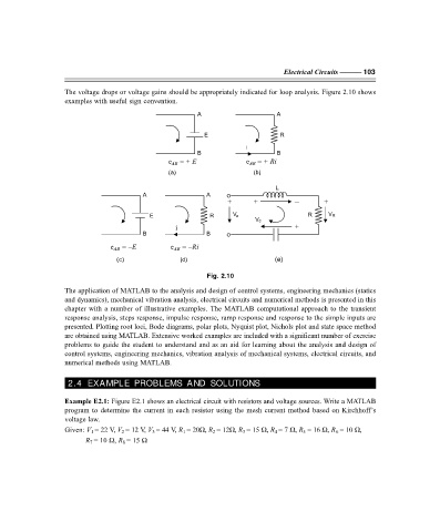
The voltage drops or voltage gains should be appropriately indicated for loop analysis. Figure 2.10 shows
examples with useful sign convention.
A A
E R
i
B B
e AB = + E e AB = + Ri
(a) (b)
L
A A
+ + – +
E R V a R V R
V c
i – – + –
B B
e AB = –E e AB = –Ri
(c) (d) (e)
Fig. 2.10
The application of MATLAB to the analysis and design of control systems, engineering mechanics (statics
and dynamics), mechanical vibration analysis, electrical circuits and numerical methods is presented in this
chapter with a number of illustrative examples. The MATLAB computational approach to the transient
response analysis, steps response, impulse response, ramp response and response to the simple inputs are
presented. Plotting root loci, Bode diagrams, polar plots, Nyquist plot, Nichols plot and state space method
are obtained using MATLAB. Extensive worked examples are included with a significant number of exercise
problems to guide the student to understand and as an aid for learning about the analysis and design of
control systems, engineering mechanics, vibration analysis of mechanical systems, electrical circuits, and
numerical methods using MATLAB.
2.4 EXAMPLE PROBLEMS AND SOLUTIONS
Example E2.1: Figure E2.1 shows an electrical circuit with resistors and voltage sources. Write a MATLAB
program to determine the current in each resistor using the mesh current method based on Kirchhoff’s
voltage law.
Given: V 1 = 22 V, V 2 = 12 V, V 3 = 44 V, R 1 = 20Ω, R 2 = 12Ω, R 3 = 15 Ω, R 4 = 7 Ω, R 5 = 16 Ω, R 6 = 10 Ω,
R 7 = 10 Ω, R 8 = 15 Ω
F:\Final Book\Sanjay\IIIrd Printout\Dt. 10-03-09