
Page 119 - MATLAB an introduction with applications
P. 119
104 ——— MATLAB: An Introduction with Applications
R 1
i 1
V 1 +
R 2 R 3
i 2 i 3 + V 2
R 4
R 6
R 5
i 4 -
R 7 V 3
R 8
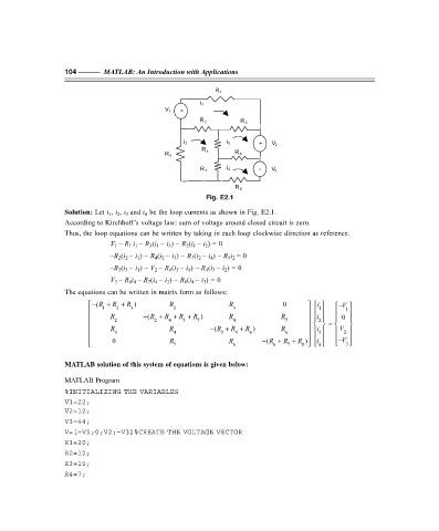
Fig. E2.1
Solution: Let i 1 , i 2 , i 3 and i 4 be the loop currents as shown in Fig. E2.1.
According to Kirchhoff’s voltage law: sum of voltage around closed circuit is zero.
Thus, the loop equations can be written by taking in each loop clockwise direction as reference.
V 1 – R 1 i 1 – R 3 (i 1 – i 3 ) – R 2 (i 1 – i 2 ) = 0
–R 2 (i 2 – i 1 ) – R 4 (i 2 – i 3 ) – R 7 (i 2 – i 4 ) – R 5 i 2 = 0
–R 3 (i 3 – i 1 ) – V 2 – R 6 (i 3 – i 4 ) – R 4 (i 3 – i 2 ) = 0
V 3 – R 8 i 4 – R 7 (i 4 – i 2 ) – R 6 (i 4 – i 3 ) = 0
The equations can be written in matrix form as follows:
− (R + R + R ) R R 0 i − V
1
1 2 3 2 3 1
i
R 2 − (R + R + R + R 7 ) R 4 R 7 0
2
5
4
2
R R − (R + R + R ) R = V
i
3 4 3 4 6 6 2
3
0 R R − (R + R + R ) − V
i
7 6 6 7 8 3
4
MATLAB solution of this system of equations is given below:
MATLAB Program
%INITIALIZING THE VARIABLES
V1=22;
V2=12;
V3=44;
V=[–V1;0;V2;–V3]%CREATE THE VOLTAGE VECTOR
R1=20;
R2=12;
R3=15;
R4=7;
F:\Final Book\Sanjay\IIIrd Printout\Dt. 10-03-09