
Page 108 - MEMS Mechanical Sensors
P. 108
5.5 Resonant Techniques 97
This Doppler frequency shift from a moving target can therefore be used as the
basis of a detection technique of the velocity of the target. Laser Doppler velocime-
try is a well-established field of research. Frequency variation is converted into
intensity variation by interferometry by combining a nonfrequency-shifted refer-
ence beam with the shifted beam.
5.4.6 Polarization
Linear polarization is defined by the direction of the electric vector of the electro-
magnetic wave. Circular polarized light is defined by the direction of rotation of the
electric field vector when viewed looking towards the source. Any polarization can
be resolved into two orthogonal modes, and sensing can be achieved by altering the
optical path length traversed by one mode with respect to the other. In practice this
is normally achieved by a relative modification of the refractive index. A polarized
light source such as a laser is required and the photodetector must be made polariza-
tion sensitive by including a polarizer.
Polarization-based interrogation of microsensors has not been widely investi-
gated owing to the limited sensitivity available, as it is a differential technique. In
addition, the method is susceptible to intensity changes in the source.
5.5 Resonant Techniques
A resonator is a mechanical structure designed to vibrate at a particular resonant
frequency. Resonators can be fabricated from a range of single crystal materials
with micron-sized dimensions using various micromachining processes. The reso-
nant frequencies of such microresonators are extremely stable, enabling them to be
used as a time base (the quartz tuning fork in watches, for example) or as the sensing
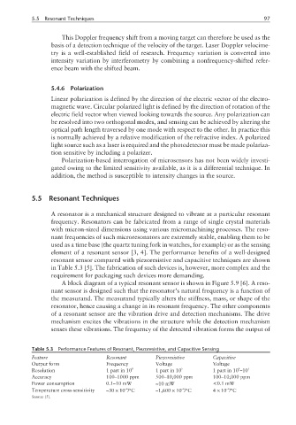
element of a resonant sensor [3, 4]. The performance benefits of a well-designed
resonant sensor compared with piezoresistive and capacitive techniques are shown
in Table 5.3 [5]. The fabrication of such devices is, however, more complex and the
requirement for packaging such devices more demanding.
A block diagram of a typical resonant sensor is shown in Figure 5.9 [6]. A reso-
nant sensor is designed such that the resonator’s natural frequency is a function of
the measurand. The measurand typically alters the stiffness, mass, or shape of the
resonator, hence causing a change in its resonant frequency. The other components
of a resonant sensor are the vibration drive and detection mechanisms. The drive
mechanism excites the vibrations in the structure while the detection mechanism
senses these vibrations. The frequency of the detected vibration forms the output of
Table 5.3 Performance Features of Resonant, Piezoresistive, and Capacitive Sensing
Feature Resonant Piezoresistive Capacitive
Output form Frequency Voltage Voltage
4
Resolution 1 part in 10 8 1 part in 10 5 1 part in 10 –10 5
Accuracy 100–1000 ppm 500–10,000 ppm 100–10,000 ppm
Power consumption 0.1–10 mW ≈10 mW <0.1 mW
–6
–6
Temperature cross-sensitivity –30 × 10 /°C –1,600 × 10 /°C 4 × 10 /°C
–6
Source: [5].