
Page 112 - MEMS Mechanical Sensors
P. 112
5.5 Resonant Techniques 101
of the oscillating resonator with the surrounding gas. There are several distinguish-
able loss mechanisms and associated effects. The magnitude of each depends pri-
marily upon the nature of the gas, surrounding gas pressure, size and shape of the
resonator, the direction of its vibrations, and its proximity to adjacent surfaces. Gas
damping effects can be negated completely by operating the resonator in a suitable
vacuum, and this is used in most micromechanical resonator applications.
Molecular damping occurs at low pressures of between 1 and 100 Pa when the
surrounding gas molecules act independently of one another [9]. The damping
effect arises from the collisions between the molecules and the resonator’s surface
as it vibrates. This causes the resonator and molecules to exchange momentum
according to their relative velocities. The magnitude of the loss is directly propor-
tional to the surrounding fluid pressure, and also close proximity of the oscillating
structure to adjacent surfaces will exaggerate the damping effects. Viscous damp-
ing predominates at pressures above 100 Pa where the molecules can no longer be
assumed to act independently and the surrounding gas must be considered as a vis-
cous fluid. Viscous drag occurs as the fluid travels over the surface of the resonator.
The formation of boundary layer around the resonator can also result in the vibra-
tions forming a transverse wave, which travels into the fluid medium. Other damp-
ing mechanisms associated with surrounding fluids are acoustic radiation and
squeezed film damping.
Structural damping, 1/Q , is associated with the energy coupled from the reso-
s
nator through its supports to the surrounding structure and must be minimized by
careful design of the resonant structure. Minimizing the energy lost from the resona-
tor to its surroundings can be achieved by a designing a balanced resonant structure,
supporting the resonator at its nodes, or by employing a decoupling system between
the resonator and its support.
The coupling mechanism between the resonator and its support can be illus-
trated by observing a fixed-fixed beam vibrating in its fundamental mode. Follow-
ing Newton’s second law that every action has an equal and opposite reaction, the
reaction to the beam’s vibrations is provided by its supports. The reaction causes the
supports to deflect and as a result energy is lost from the resonator.
The degree of coupling of a fixed-fixed beam can be reduced by operating it in a
higher-order mode. For example, the second mode in the plane of vibrations shown
above will possess a node halfway along the length of the beam. The beam will
vibrate in antiphase either side of the node, and the reactions from each half of the
beam will cancel out at the node. There will inevitably still be a reaction at each sup-
port, but the magnitude of each reaction will be less than for mode 1. The use of
such higher order modes is limited by their reduced sensitivity to applied stresses
and the fact there will always be a certain degree of coupling.
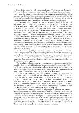
Balanced resonator designs operate on the principle of providing the reaction to
the structure’s vibrations within the resonator. Multiple-beam style resonators, for
example, incorporate this inherent dynamic moment cancellation when operated in
a balanced mode of vibration. Examples of such structures are the double-ended
tuning fork (DETF), which consists of two beams aligned alongside each other, and
the triple-beam tuning fork (TBTF), which consists of three beams aligned alongside
each other, the center tine being twice the width of the outer tines. Figure 5.11
shows these structures and their optimum modes of operation.