
Page 114 - MEMS Mechanical Sensors
P. 114
5.5 Resonant Techniques 103
In many practical cases s(y) can be represented by (5.24), the nonlinear relation-
ship being represented by the cubic term.
() =
sy s y+ s y 3 (5.24)
3
1
Placing (5.24) in (5.23), dividing through by m, and simplifying gives
ω
&& y+ s 1 m (y+ s 3 s y 3 )= F 0 cos t (5.25)
1
2
where s /m equals ω (ω representing the resonant frequency for small amplitudes
1 or or
of vibration) and s /s is denoted by β. The restoring force acting on the system is
3 1
therefore represented by
R =−ω 2 (y+ βy 3 ) (5.26)
or
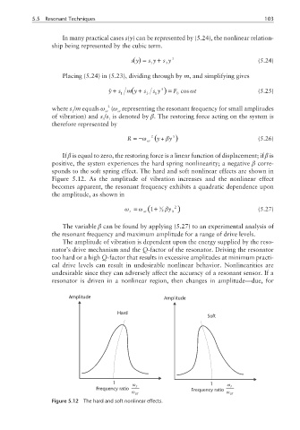
If β is equal to zero, the restoring force is a linear function of displacement; if β is
positive, the system experiences the hard spring nonlinearity; a negative β corre-
sponds to the soft spring effect. The hard and soft nonlinear effects are shown in
Figure 5.12. As the amplitude of vibration increases and the nonlinear effect
becomes apparent, the resonant frequency exhibits a quadratic dependence upon
the amplitude, as shown in
ω = ω ( +1 3 βy 2 ) (5.27)
r or 8 0
The variable β can be found by applying (5.27) to an experimental analysis of
the resonant frequency and maximum amplitude for a range of drive levels.
The amplitude of vibration is dependent upon the energy supplied by the reso-
nator’s drive mechanism and the Q-factor of the resonator. Driving the resonator
too hard or a high Q-factor that results in excessive amplitudes at minimum practi-
cal drive levels can result in undesirable nonlinear behavior. Nonlinearities are
undesirable since they can adversely affect the accuracy of a resonant sensor. If a
resonator is driven in a nonlinear region, then changes in amplitude—due, for
Amplitude Amplitude
Hard
Soft
1 ω 1 ω
Frequency ratio r Frequency ratio r
ω or ω or
Figure 5.12 The hard and soft nonlinear effects.