
Page 104 - MEMS Mechanical Sensors
P. 104
5.3 Capacitive Techniques 93
For a simple parallel plate capacitor structure, ignoring fringing fields, the
capacitance is given by
εε A
C = 0 r () F (5.17)
d
where ε is the permittivity of free space, ε is the relative permittivity of the material
0 r
between the plates, A is the area of overlap between the electrodes, and d is the sepa-
ration between the electrodes. The equation shows that the capacitance can be var-
ied by changing one or more of the other variables. Figure 5.5(a) shows the simple
case where the lower electrode is fixed and the upper electrode moves. In this case
the separation, d, is changing and hence the capacitance varies in a nonlinear man-
ner. Figure 5.5(b) depicts a device where the separation is fixed and the area of over-
lap is varied. In this configuration, there is a linear relationship between the
capacitance and area of overlap. Figure 5.5(c) shows a structure that has both a
fixed electrode distance and area of overlap. The movement is applied to a dielec-
tric material (of permittivity ε ) sandwiched between two electrodes. A common
2
problem to all of these devices is that temperature will affect all three sensing
parameters (d, A, and ε ), resulting in changes in the signal output. This effect must
r
be compensated for in some manner, whether by additional signal conditioning cir-
cuitry or, preferably, by geometric design.
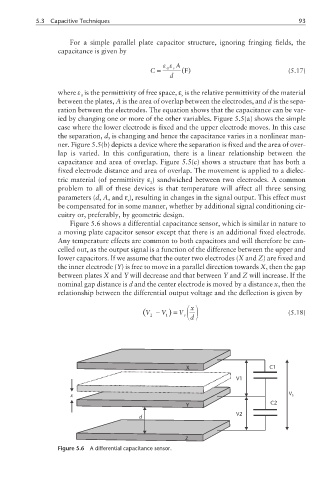
Figure 5.6 shows a differential capacitance sensor, which is similar in nature to
a moving plate capacitor sensor except that there is an additional fixed electrode.
Any temperature effects are common to both capacitors and will therefore be can-
celled out, as the output signal is a function of the difference between the upper and
lower capacitors. If we assume that the outer two electrodes (X and Z) are fixed and
the inner electrode (Y) is free to move in a parallel direction towards X, then the gap
between plates X and Y will decrease and that between Y and Z will increase. If the
nominal gap distance is d and the center electrode is moved by a distance x, then the
relationship between the differential output voltage and the deflection is given by
x
(V − V )= V (5.18)
2 1 s d
X C1
V1
x V s
Y C2
V2
d
Z
Figure 5.6 A differential capacitance sensor.