
Page 99 - MEMS Mechanical Sensors
P. 99
88 Mechanical Transduction Techniques
the contribution to the gauge factor from the geometric effect is therefore between
1.4 and 1.6. Sensors that exhibit a change in resistance as a result of an applied strain
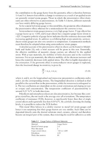
are generally termed strain gauges. Those in which the piezoresistive effect domi-
nates are often referred to as piezoresistors. As Table 5.1 shows, different materials
can have widely differing gauge factors.
So for a metal foil strain gauge or thin metal film, the geometric effect dominates
the piezoresistive effect; whereas for a semiconductor the converse is true.
Semiconductor strain gauges possess a very high gauge factor. P-type silicon has
a gauge factor up to +200, and n-type silicon has a negative gauge factor down to
–125. A negative polarity of gauge factor indicates that the resistance decreases with
increasing applied strain. In addition to exhibiting high strain sensitivity, semicon-
ductor strain gauges are also very sensitive to temperature. Compensation methods
must therefore be adopted when using semiconductor strain gauges.
A detailed account of the piezoresistive effect in silicon can be found in Middel-
hoek and Audet [1]; only a brief account will be given in this text. Essentially,
the effective mobilities of majority charge carriers are affected by the applied
stress. With p-type materials, the mobility of holes decreases and so the resistivity
increases. For n-type materials, the effective mobility of the electrons increases and
hence the resistivity decreases with applied stress. The effect is highly dependent on
the orientation. If the geometric effect in semiconductor strain gauges is neglected,
then the fractional change in resistivity is given by
dρ
= πσ + πσ (5.10)
p l l t t
where π and π are the longitudinal and transverse piezoresistive coefficients and σ
l t l
and σ are the corresponding stresses. The longitudinal direction is defined as that
t
parallel to the current flow in the piezoresistor, while the transverse is orthogonal to
it. The two coefficients are dependent on the crystal orientation and doping (p-type
or n-type) and concentration. The temperature coefficient of piezoresistivity is
around 0.25 %/°C in both directions.
Polysilicon and amorphous silicon are also piezoresistive, but because they com-
prise crystallites, the net result is the average over all orientations. The temperature
coefficient of resistance (TCR), however, is significantly lower than that of single
crystal silicon and is generally less than 0.05%/°C. By carefully choosing the doping
levels, it is possible to reduce the TCR further.
Thin metal films behave in a similar manner to metal foil strain gauges and
hence it not surprising that their gauge factors are very similar. Such films can be
deposited directly onto the desired substrate (steel, ceramic, silicon) and therefore
become an integral part of the system, thus removing the need for adhesives as with
Table 5.1 Gauge Factors of Different Materials
Material Gauge Factor
Metal foil strain gauge 2–5
Thin-film metal 2
Single crystal silicon –125 to +200
Polysilicon ±30
Thick-film resistors 10