
Page 96 - MEMS Mechanical Sensors
P. 96
CHAPTER 5
Mechanical Transduction Techniques
There are many examples of micromachined mechanical transducers and these will
be reviewed in detail in the following chapters. The purpose of this chapter is to pres-
ent some of the fundamental concepts and techniques that are used in the design of
mechanical microsensors and actuators. The most sensing-important mechanisms
include the following effects: piezoresistivity, piezoelectricity, variable capacitance,
optical, and resonant techniques. We will also review the main actuation methods,
including: electrostatic, piezoelectric, thermal, and magnetic. The final section of this
chapter includes a review of so-called intelligent (or smart) sensors.
5.1 Piezoresistivity
Piezoresistivity derives its name from the Greek word piezin, meaning “to press.” It
is an effect exhibited by various materials that exhibit a change in resistivity due to
an applied pressure. The effect was first discovered by Lord Kelvin in 1856, who
noted that the resistance of copper and iron wires increased when in tension. He
also observed that iron wires showed a larger change in resistance than those made
of copper. The first application of the piezoresistive effect did not appear until the
1930s, some 75 years after Lord Kelvin’s discovery. Rather than using metal wires,
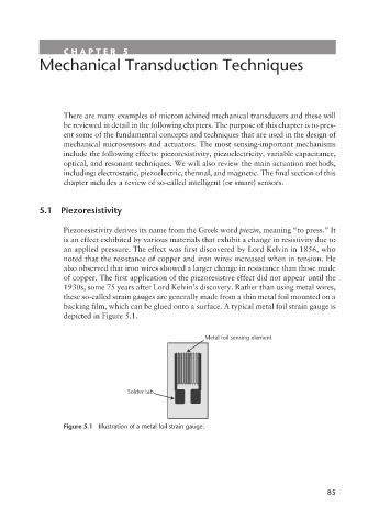
these so-called strain gauges are generally made from a thin metal foil mounted on a
backing film, which can be glued onto a surface. A typical metal foil strain gauge is
depicted in Figure 5.1.
Metal foil sensing element
Solder tab
Figure 5.1 Illustration of a metal foil strain gauge.
85