
Page 103 - MEMS Mechanical Sensors
P. 103
92 Mechanical Transduction Techniques
impedance
L C1 R
Log
f r f a Frequency
C2
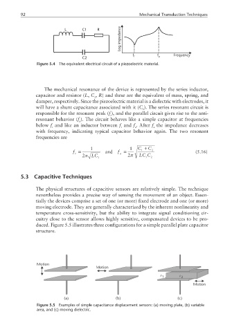
Figure 5.4 The equivalent electrical circuit of a piezoelectric material.
The mechanical resonance of the device is represented by the series inductor,
capacitor and resistor (L, C , R) and these are the equivalent of mass, spring, and
1
damper, respectively. Since the piezoelectric material is a dielectric with electrodes, it
will have a shunt capacitance associated with it (C ). The series resonant circuit is
2
responsible for the resonant peak (f ), and the parallel circuit gives rise to the anti-
r
resonant behavior (f ). The circuit behaves like a simple capacitor at frequencies
a
below f and like an inductor between f and f . After f the impedance decreases
r r a a
with frequency, indicating typical capacitor behavior again. The two resonant
frequencies are
1 1 C + C
f = and f = 1 2 (5.16)
r a
2π LC 1 2π LC C 2
1
5.3 Capacitive Techniques
The physical structures of capacitive sensors are relatively simple. The technique
nevertheless provides a precise way of sensing the movement of an object. Essen-
tially the devices comprise a set of one (or more) fixed electrode and one (or more)
moving electrode. They are generally characterized by the inherent nonlinearity and
temperature cross-sensitivity, but the ability to integrate signal conditioning cir-
cuitry close to the sensor allows highly sensitive, compensated devices to be pro-
duced. Figure 5.5 illustrates three configurations for a simple parallel plate capacitor
structure.
Motion
Motion
ε 1 ε 2
Motion
(a) (b) (c)
Figure 5.5 Examples of simple capacitance displacement sensors: (a) moving plate, (b) variable
area, and (c) moving dielectric.