
Page 63 - MEMS Mechanical Sensors
P. 63
52 MEMS Simulation and Design Tools
Preprocessor Solution Postprocessor
Element type Analysis type Read results
Material properties Define loads by set
Define geometry Load set options by load step
Mesh attributes Solve by time/frequency
Model checking View element/nodal results
Save results (prestress and
fatigue analysis)
Figure 3.10 Typical ANSYS routine.
1
1 1 1 1 ANSYS
1 1 1
1 1
1 1
1 1 1 1
1 1 1 1 1 1
1 1 1 1
1 1 1 1
1 1 1
1
1 1 1 2 1 1 1 1 1 1
2 2 2 1 1 1
2 2 1 1
2 2 1
2 2 1
2
1 2 2
1 2
2
2 2 2 1
1 2 1 1
1 2 1
1 1 1 1 1
1 1 1 1
1 1
1 1 1 1 1
1 1
1 1 1 1
1 1 1 1
1 1 1
1
1
1 1 1 1
1 1 1 1 1
1
1
1 1 1 1 1 1
1 1
1
Thick-film PST/Silicon Accelerometer -1g in s 1 1 1 1 1 1
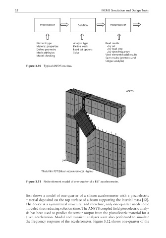
Figure 3.11 Finite element model of one-quarter of a PZT accelerometer.
first shows a model of one-quarter of a silicon accelerometer with a piezoelectric
material deposited on the top surface of a beam supporting the inertial mass [12].
The device is a symmetrical structure, and therefore, only one-quarter needs to be
modeled thus reducing solution time. The ANSYS coupled field piezoelectric analy-
sis has been used to predict the sensor output from the piezoelectric material for a
given acceleration. Modal and transient analyses were also performed to simulate
the frequency response of the accelerometer. Figure 3.12 shows one-quarter of the