
Page 62 - MEMS Mechanical Sensors
P. 62
3.2 Simulation and Design Tools 51
• Structural (static, modal, harmonic, transient);
• Electrostatic effects;
• Piezoelectric films;
• Residual stresses;
• Fluidic damping;
• Microfluidics;
• Composite structures;
• Electrothermostructural coupling;
• Electromagnetic systems.
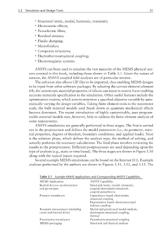
ANSYS can been used to simulate the vast majority of the MEMS physical sen-
sors covered in this book, including those shown in Table 3.1. Given the nature of
sensors, the ANSYS coupled field analyses are of particular interest.
The software also allows CIF files to be imported, thus enabling MEMS designs
to be input from other software packages. By selecting the correct element (element
64), the anisotropic material properties of silicon can input in matrix form enabling
accurate materials specification in the simulation. Other useful features include the
optimization routine, which aims to minimize a specified objective variable by auto-
matically varying the design variables. Taking finite element tools to the nanometer
scale, the bulk material models used break down as quantum mechanical effects
become dominant. The recent introduction of highly customizable, user program-
mable material models may, however, help to address the finite element analysis of
some nanosystems.
ANSYS simulations are generally performed in three stages. The first is carried
out in the preprocessor and defines the model parameters (i.e., its geometry, mate-
rial properties, degrees of freedom, boundary conditions, and applied loads). Next
is the solution phase, which defines the analysis type, the method of solving, and
actually performs the necessary calculations. The final phase involves reviewing the
results in the postprocessor. Different postprocessors are used depending upon the
type of analysis (e.g., static or time based). The three stages are shown in Figure 3.10
along with the typical inputs required.
Several example MEMS simulations can be found on the Internet [11]. Example
analyses performed by the authors are shown in Figures 3.11, 3.12, and 3.13. The
Table 3.1 Example MEMS Applications and Corresponding ANSYS Capabilities
MEMS Application ANSYS Capability
Inertial devices: accelerometers Structural (static, modal, transient),
and gyroscopes coupled electrostatic-structural,
coupled piezoelectric
Pressure transducers Capacitance based: electrostatic
structural coupling
Piezoresistive based: electrostructural
indirect coupling
Resonant microsensors (including Modal and prestressed modal analysis,
comb and thermal drive) electrostatic-structural coupling,
thermal
Piezoelectric transducers Piezoelectric-structural coupling
MEMS packaging Structural and thermal analysis