
Page 72 - MEMS Mechanical Sensors
P. 72
4.3 Packaging Processes 61
common wire and pad materials, are summarized in Table 4.1. Ball bonding most
commonly uses relatively thin gold wire (< 75 µm) because it deforms readily
under pressure and temperature, it resists oxide formation, and is well suited to
the ball formation and cutting process. Gold wire is also attractive because
it remains inert after bonding and does not require hermetic sealing. Ball bond-
ing requires a pad pitch of more than 100 µm. Wedge bonding, on the other
hand, can be used for both aluminum wire and gold wire bonding applications.
Aluminum wire is bonded in an ultrasonic bonding process at room temperature.
Gold wire wedge bonding uses a thermo-sonic bonding process. An advantage of
wedge bonding is that it can be used on pads with a pitch of just 50 µm. It is how-
ever slower than thermo-sonic ball bonding. Aluminum ultrasonic bonding is the
most common wedge bonding process because of the low cost and the low working
temperature.
4.3.1.2 Tape Automated Bonding
In the case of tape automated bonding (TAB), the interconnections are first pat-
terned on a multilayer polymer tape. The tape is positioned above the bare die so
that the metal tracks on the polymer tape correspond to the contact pads on the die.
Traditionally, the contact pads are located around the edge of the die, but a more
recent innovation known as area TAB has contact pads in the form of metal bumps
that are distributed over the entire surface of the die. This approach is able to sup-
port a greater number of connections to and from the die.
The TAB technology has several advantages over the wire bonding approach.
These advantages include a smaller bonding pad and therefore increased I/O counts,
smaller on-chip bonding pitch than for ball wire bonding (100 µm), an increased
productivity rate, reduced electrical noise, suitability for higher frequency applica-
tions, lower labor costs, and lighter weight. The disadvantages of TAB technology
include the time and cost of designing and fabricating the tape and the capital
expense of the TAB bonding equipment. In addition, each die must have its own
tape patterned for its pad and package configuration. For these reasons, TAB has
typically been limited to high-volume production applications.
4.3.1.3 Flip Chip
Flip chip assembly, also called direct chip attach (DCA), involves placing the die
face-down (hence, “flipped”) onto the package or circuit board. The electrical con-
nection is made by conductive bumps formed on the die bond pads. Flip chip assem-
bly is predominantly being used for ICs, but MEMS devices are beginning to be
developed in flip chip form. The advantages of flip chip include:
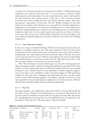
Table 4.1 Summary of Wire Bonding Processes
Wire Bonding Technique Pressure Temp. Ultrasonic Wire Pad Speed
Process (°C) (Wires/Sec)
Ball Thermo-compression High 300–500 No Au Al, Au
Ball Thermo-sonic Low 100–150 Yes Au Al, Au 10
Wedge Thermo-sonic Low 100–150 Yes Au, Al Al, Au 4
Wedge Ultrasonic Low 25 Yes Au Al, Au 4