
Page 162 - MEMS and Microstructures in Aerospace Applications
P. 162
Osiander / MEMS and microstructures in Aerospace applications DK3181_c008 Final Proof page 152 1.9.2005 12:05pm
152 MEMS and Microstructures in Aerospace Applications
V control
V in V out V in V out
V control
Series Shunt
Configuration Configuration
FIGURE 8.1 Different configurations for microwave switches.
Drive capacitor
Unbiased - OFF
Spring
RF line RF line Biased - ON
Contact
Anchor Cross section
shunt
through bridge
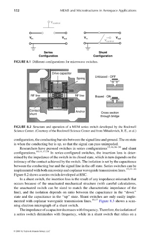
FIGURE 8.2 Structure and operation of a MEM series switch developed by the Rockwell
Science Center. (Courtesy of the Rockwell Science Center and from Mihailovich, R. E., et al.)
configuration, the conducting bar sits between the signal line and ground. The on state
is when the conducting bar is up, so that the signal can pass unimpeded.
15,16,26–30
Researchers have pursued switches in series configurations and shunt
10,11,17,18
configurations. In series-configured switches, the insertion loss is deter-
mined by the impedance of the switch in its closed state, which in turn depends on the
intimacy of the contact achieved by the switch. The isolation is set by the capacitance
between the conducting bar and the signal line in the off state. Series switches can be
implemented with both microstrip and coplanar waveguide transmission lines. 15,31–33
Figure 8.2 shows a series switch developed at RSC.
In a shunt switch, the insertion loss is the result of any impedance mismatch that
occurs because of the unactuated mechanical structure (with careful calculations,
the unactuated switch can be sized to match the characteristic impedance of the
line), and the isolation depends on ratio between the capacitance in the ‘‘down’’
state and the capacitance in the ‘‘up’’ state. Shunt switches are only easily imple-
mented with coplanar waveguide transmission lines. 10,17 Figure 8.3 shows a scan-
ning electron micrograph of a shunt switch.
Theimpedanceofacapacitordecreaseswithfrequency.Therefore,theisolationof
a series switch diminishes with frequency, while in a shunt switch that relies on a
© 2006 by Taylor & Francis Group, LLC