
Page 163 - MEMS and Microstructures in Aerospace Applications
P. 163
Osiander / MEMS and microstructures in Aerospace applications DK3181_c008 Final Proof page 153 1.9.2005 12:05pm
Microelectromechanical Systems for Spacecraft Communications 153
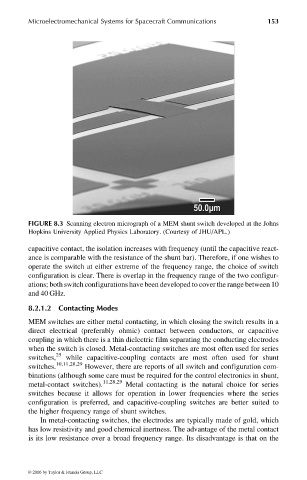
FIGURE 8.3 Scanning electron micrograph of a MEM shunt switch developed at the Johns
Hopkins University Applied Physics Laboratory. (Courtesy of JHU/APL.)
capacitive contact, the isolation increases with frequency (until the capacitive react-
ance is comparable with the resistance of the shunt bar). Therefore, if one wishes to
operate the switch at either extreme of the frequency range, the choice of switch
configuration is clear. There is overlap in the frequency range of the two configur-
ations; both switch configurations have been developed to cover the range between 10
and 40 GHz.
8.2.1.2 Contacting Modes
MEM switches are either metal contacting, in which closing the switch results in a
direct electrical (preferably ohmic) contact between conductors, or capacitive
coupling in which there is a thin dielectric film separating the conducting electrodes
when the switch is closed. Metal-contacting switches are most often used for series
switches, 25 while capacitive-coupling contacts are most often used for shunt
switches. 10,11,28,29 However, there are reports of all switch and configuration com-
binations (although some care must be required for the control electronics in shunt,
metal-contact switches). 11,28,29 Metal contacting is the natural choice for series
switches because it allows for operation in lower frequencies where the series
configuration is preferred, and capacitive-coupling switches are better suited to
the higher frequency range of shunt switches.
In metal-contacting switches, the electrodes are typically made of gold, which
has low resistivity and good chemical inertness. The advantage of the metal contact
is its low resistance over a broad frequency range. Its disadvantage is that on the
© 2006 by Taylor & Francis Group, LLC