
Page 203 - MEMS and Microstructures in Aerospace Applications
P. 203
Osiander / MEMS and microstructures in Aerospace applications DK3181_c009 Final Proof page 194 1.9.2005 12:07pm
194 MEMS and Microstructures in Aerospace Applications
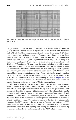
FIGURE 9.3 Shuttle arrays are on a single die, each 1.265 1.303 cm in size. (Courtesy:
JHU/APL.)
design, JHU/APL, together with NASA/GSFC and Sandia National Laboratory
(SNL), adopted a MEMS shutter design which will be flown on ST5. Fabricated
with SNL’s SUMMIT 5 process, six electrostatic comb drives, using SNL’s high-
performance design, will move an array of shutters, each 150 mm long and 6 mm
wide, to either a gold surface or the silicon substrate and changing the emissivity
from 0.6 (silicon) to < 0.1 (gold). A picture of such an array, 1767 876 mmin
size, is shown in Figure 9.3. Seventy-two of these arrays are on a single die, each
1.265 1.303 cm in size. All arrays on a die are controlled together with a supply
voltage greater than 35 V and negligible current draw. For the shutter, a single
failure may cause a short and stop the entire die from working. In order to prevent
such an issue, each array is connected to the supply bus via a MEMS fuse, which
can be blown with a current of greater than 17 mA. Note that for normal operation,
the current is minimal and the dc leakage current has been determined to be
< 80 mA. A picture of the final radiator assembly is shown in Figure 9.4. Each
radiator, 9 10 in size, contains 6 AlC substrates; which themselves contain six
shutter dies each, adding up to a total of 36 dies on the radiator.
The VEC Instrument consists of two components, the previously described
MEMS Shutter Array (MSA) radiator and the Electronic Control Unit (ECU).
The MSA radiator is physically located on the top deck of the spin-stabilized ST5
spacecraft. The ECU is located within the spacecraft. The MSA radiator can be
operated in both manual and autonomous mode, to automatically evaluate both high
and low emittance states in a given test sequence as well as via ground control. A
1.5 W electrical heater is included in order to provide calibrated measurements of
effective emittance changes. The radiator is located so that it receives minimal solar
exposure. The MSA radiator is thermally isolated from the spacecraft, as the VEC
technologies on this mission are for technology validation only. The thermal
performance associated with opening and closing the shutters is measured by
thermistors that are located on the underside of the MSA radiator chassis.
© 2006 by Taylor & Francis Group, LLC