
Page 205 - MEMS and Microstructures in Aerospace Applications
P. 205
Osiander / MEMS and microstructures in Aerospace applications DK3181_c009 Final Proof page 196 1.9.2005 12:07pm
196 MEMS and Microstructures in Aerospace Applications
Polymer
Radiator
Supports Substrate Gold Sputtered Nitride
(SU8) Membrane (Electrically Insulating)
FIGURE 9.5 A schematic of SU8 fabricated device.
electrostatically attracted to the radiator and makes thermal contact, connecting the
radiator to the high emissivity surface. The disadvantage of this design is the high
switching voltage, typically greater than 400 V.
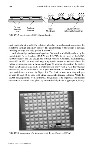
A similar design has been developed and fabricated in a MEMS platform by the
United States Naval Academy (USNA) and JHU/APL, to be flown on the USNA
Midstar satellite. For this design, the radiator consists of an array of membranes,
about 400 to 500 mm wide and long, suspended a couple of microns above the
surface on frames or posts at the corner. Figure 9.5 shows a schematic of the device,
which is fabricated using SU8, a photosensitive epoxy with a very low thermal
conductivity in the cured state, and a gold membrane. An example of a frame-
supported device is shown in Figure 9.6. The devices have switching voltages
between 20 and 40 V, very well within spacecraft standard voltages. While the
MEMS design performs well, the thermal design needs to be improved. The thermal
conductance in the off state, given by the conductivity in the support posts, is very
FIGURE 9.6 An example of a frame-supported device. (Courtesy: USNA.)
© 2006 by Taylor & Francis Group, LLC