
Page 261 - MEMS and Microstructures in Aerospace Applications
P. 261
Osiander / MEMS and microstructures in Aerospace applications DK3181_c011 Final Proof page 252 1.9.2005 12:31pm
252 MEMS and Microstructures in Aerospace Applications
where A t represents the area of the throat of the nozzle, a is the velocity of sound,
and r 0 is the density of the medium inside the tank. As can be seen from these
equations, the nozzle design and the parameters of the tank medium, like pressure or
temperature determine the performance of the thruster.
Using these equations, it is possible to calculate the performance of a sample
resistojet. Assuming the gas is heated to 1200 K and the gas is purely molecular
hydrogen (k ¼ 1.67), the maximum exit velocity will amount to 5000 m/sec and the
2
6
resulting thrust for a pressure of 2.10 Pa and a throat diameter of 1 mm would
amount to approximately 3/N.
Resistojets allow for the use of liquids — which are vaporized in the system —
as a propellant. This simplifies storage and flow control compared to pure gaseous
systems. Therefore, miniaturized versions of the resistojet very often use water
vapor instead of hydrogen, which enables operation at lower pressures and a smaller
system. Thrust values of 500 mN and exit velocities of 990 m/s are typical. The
reduction in velocity is not only due to lower pressures in the system but is also
affected by the decreasing influence of the nozzle with increasing Knudsen number
as pointed out in the introduction.
11.2.6.2 System Requirements
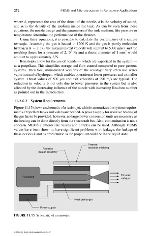
Figure 11.15 shows a schematic of a resistojet, which summarizes the system require-
ments. Propellant tanks and valves are needed. A power supply for resistive heating of
the gas has to be provided, however, no large power conversion units are necessary as
the heating can be done directly from the spacecraft bus. Also, contamination is not a
concern. MEMS elements like valves and nozzles can be used. Although MEMS
valves have been shown to have significant problems with leakage, the leakage of
these devices is not as problematic as the propellant could be in the liquid state.
Thermal
radiation shielding
Resistive
heater assembly
Thruster
Propellant
exhaust
Heat exchanger
Power supply
FIGURE 11.15 Schematic of a resistojet.
© 2006 by Taylor & Francis Group, LLC