
Page 257 - MEMS and Microstructures in Aerospace Applications
P. 257
Osiander / MEMS and microstructures in Aerospace applications DK3181_c011 Final Proof page 248 1.9.2005 12:31pm
248 MEMS and Microstructures in Aerospace Applications
11.2.5.1 Principle of Operation
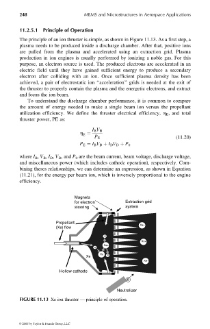
The principle of an ion thruster is simple, as shown in Figure 11.13. As a first step, a
plasma needs to be produced inside a discharge chamber. After that, positive ions
are pulled from the plasma and accelerated using an extraction grid. Plasma
production in ion engines is usually performed by ionizing a noble gas. For this
purpose, an electron source is used. The produced electrons are accelerated in an
electric field until they have gained sufficient energy to produce a secondary
electron after colliding with an ion. Once sufficient plasma density has been
achieved, a pair of electrostatic ion ‘‘acceleration’’ grids is needed at the exit of
the thruster to properly contain the plasma and the energetic electrons, and extract
and focus the ion beam.
To understand the discharge chamber performance, it is common to compare
the amount of energy needed to make a single beam ion versus the propellant
utilization efficiency. We define the thruster electrical efficiency, h E , and total
thruster power, PE as:
I B V B
h ¼
E
P E (11:20)
P E ¼ I B V B þ I D V D þ P 0
where I B , V B , I D , V D , and P 0 are the beam current, beam voltage, discharge voltage,
and miscellaneous power (which includes cathode operation), respectively. Com-
bining theses relationships, we can determine an expression, as shown in Equation
(11.21), for the energy per beam ion, which is inversely proportional to the engine
efficiency.
Magnets
for electron Extraction grid
steering system
Propellant
(Xe) flow Xe+
e
Xe+
Xe+
e
Xe e
Xe
Xe+
Hollow cathode
e
Neutralizer
FIGURE 11.13 Xe ion thruster — principle of operation.
© 2006 by Taylor & Francis Group, LLC