
Page 254 - MEMS and Microstructures in Aerospace Applications
P. 254
Osiander / MEMS and microstructures in Aerospace applications DK3181_c011 Final Proof page 245 1.9.2005 12:31pm
Micropropulsion Technologies 245
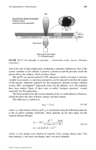
JET
Transmission Mode Illumination
Protects optics
Improves device geometry
140 µm
hole
~
Ablatant t ~ 160 µm
1
~
Transparent substrate, e.g., acetate film, is not penetrated t 2 ~ 80 µm
Fast lenses
Rep-pulsed laser diode
(1−5 W peak power)
FIGURE 11.11 LAT principle of operation — transmission mode. (Source: Photonics
Associates.)
side of the tape to high temperature, producing a miniature ablation jet. Part of the
acetate substrate is also ablated. A plasma is produced and the pressure inside the
plasma drives the exhaust, which produces thrust.
The mLPT can operate pulsed or CW, and power density on target is optically
variable in an instant, so operating parameters can be adjusted to throttle the output
of the thruster. Materials explored for the transparent substrate include cellulose
acetate, PET, and Kaptone polyimide resin. For the ablatant, over 160 materials
have been studied. Many of these were so-called ‘‘designer materials’’ created
especially for this application.
The thrust produced by this system depends on the so-called ablation efficiency,
which describes the ratio of kinetic energy and laser energy.
This efficiency is defined as:
h AB ¼ C m v E (11:16)
where v E is the exhaust velocity and C m as calculated, using the following equation,
is the so-called coupling coefficient, which depends on the laser input and the
material ablated through:
c 9=16 mN
C m ¼ 58:3 p ffiffiffi
A 1=8 (Il t) 1=4 W (11:17)
2
c ¼ (A=2)(Z (Z þ 1)) 1=3
where A is the atomic mass number of material, Z the average charge state, I the
laser intensity, l the laser wavelength, and t the pulse duration.
© 2006 by Taylor & Francis Group, LLC