
Page 252 - MEMS and Microstructures in Aerospace Applications
P. 252
Osiander / MEMS and microstructures in Aerospace applications DK3181_c011 Final Proof page 243 1.9.2005 12:31pm
Micropropulsion Technologies 243
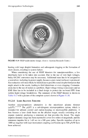
FIGURE 11.9 FEEP multi-emitter design. (Source: Austrian Research Centre.)
heating with large droplet formation and subsequent clogging or the formation of
short circuits, resulting in system failure.
When considering the use of FEEP thrusters for nano/picosatellites, a few
drawbacks have to be taken into account. Due to the use of very high voltages,
bulky DC/DC converters may be necessary. Additional mass has to be assigned to
a neutralizer, including its power supply, because a pure metal ion beam is produced.
Size reduction will most likely be limited due to possible metal droplet formation that
might attach to the anode, leading to field distortions or even clogging. Contamin-
ation due to the use of metals is a problem. High-voltage wiring is necessary and an
EMI filter has to be included in a final design to protect the on-board PPU from
sudden high-voltage breakdowns. The summary of the FEEP thruster is shown in
Table 11.3 with a picture of the complete system shown in Figure 11.10.
11.2.4 LASER ABLATION THRUSTER
Another micropropulsion alternative is the microlaser plasma thruster
(mLPT). 17,27,28 The mLPT is a sub-kilogram micropropulsion option, which is
intended for attitude control and station-keeping on microsatellite platforms. A
lens focuses a laser diode beam on the ablation target, usually consisting of an
organic material, producing a miniature jet that provides the thrust. The single
impulse dynamic range has been reported to cover five orders of magnitude, and the
minimum impulse bit is 1 nN sec in a 100 msec pulse. Specific impulses of up to
1000 sec together with laser momentum coupling coefficients up to 500 mN/W have
been achieved.
© 2006 by Taylor & Francis Group, LLC