
Page 253 - MEMS and Microstructures in Aerospace Applications
P. 253
Osiander / MEMS and microstructures in Aerospace applications DK3181_c011 Final Proof page 244 1.9.2005 12:31pm
244 MEMS and Microstructures in Aerospace Applications
TABLE 11.3
Performance Characteristics for FEEP Thruster
I sp 8000 to 12000 sec
I-bit (if pulsed) DC
Rep. rate (if pulsed) DC
Power 0.5 to 10 W (ARC FEEP 100)
Thrust 100 mN
Thrust or power 20 mN/W
Impulse or prop. 5 Nsec/g
Feed mechan. Yes/passive
Current system mass 500 g
(includes PPU, valve, tank, etc.)
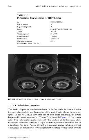
FIGURE 11.10 FEEP thruster. (Source: Austrian Research Centre.)
11.2.4.1 Principle of Operation
Two modes of operation have been evaluated. In the first mode, the laser is aimed at
the target at an angle to avoid deposition of the ablated material onto the sensitive
optics. In this case, single layer tape can be used. More commonly, the device
is operated in transmission mode (‘‘T-mode’’), as shown in Figure 11.11, to protect
optics from solid contaminants produced by the ablation jet. In this mode, a lens
focuses the laser diode output to a 25-mm diameter spot on the transparent side of
a two-layer fuel tape. Passing through a transparent acetate substrate without
damaging it, the beam heats a specially prepared absorbing coating on the opposite
© 2006 by Taylor & Francis Group, LLC