
Page 262 - MEMS and Microstructures in Aerospace Applications
P. 262
Osiander / MEMS and microstructures in Aerospace applications DK3181_c011 Final Proof page 253 1.9.2005 12:31pm
Micropropulsion Technologies 253
TABLE 11.6
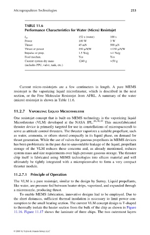
Performance Characteristics for Water (Micro) Resistojet
I sp 152 s (water) 100 s
Power 100 W 3 W
Thrust 45 mN 500 mN
Thrust or power 450 mN/W 150 mN/W
Impulse or prop. 1.5 Ns/g 1 Ns/g
Feed mechan. Yes Yes
Current system dry mass 1240 g 50 g
(includes PPU, valve, tank, etc.)
Current micro-resistojets are a few centimeters in length. A pure MEMS
resistojet is the vaporizing liquid microthruster, which is described in the next
section, or the Free Molecular Resistojet from AFRL. A summary of the water
(micro) resistojet is shown in Table 11.6.
11.2.7 VAPORIZING LIQUID MICROTHRUSTER
One resistojet concept that is built on MEMS technology is the vaporizing liquid
26,38,39
Microthruster (VLM) developed at the NASA JPL. This microfabricated
thruster device is primarily targeted for use in constellations of microspacecraft to
serve as attitude control thrusters. The thruster vaporizes a suitable propellant, such
as water, ammonia, or others stored compactly in its liquid phase, on demand for
thrust generation. While the use of valves for gaseous propellants in MEMS devices
has been problematic in the past due to unavoidable leakage of the liquid, propellant
storage of the VLM reduces these concerns and, as already mentioned, reduces
system mass and size requirements over high-pressure gaseous storage. The thruster
chip itself is fabricated using MEMS technologies into silicon material and will
ultimately be tightly integrated with a micropiezovalve to form a very compact
thruster module.
11.2.7.1 Principle of Operation
The VLM is a pure resistojet, similar to the design by Surrey. Liquid propellants,
like water, are pressure-fed between heater strips, vaporized, and expanded through
a micronozzle, producing thrust.
To enable MEMS fabrication, innovative designs had to be employed. Due to
the short distances, sufficient thermal insulation is necessary to limit power con-
sumption to the small heating section. The current VLM concept design is T-shaped
to thermally isolate the heater section from the bulk of the chip as shown in Figure
11.16. Figure 11.17 shows the laminate of three chips. The two outermost layers
© 2006 by Taylor & Francis Group, LLC