
Page 264 - MEMS and Microstructures in Aerospace Applications
P. 264
Osiander / MEMS and microstructures in Aerospace applications DK3181_c011 Final Proof page 255 1.9.2005 12:31pm
Micropropulsion Technologies 255
silicon barrier. An electric current is passed through the barrier, resistively
heating and melting it. However, cracking of the barrier has been observed due to
thermal shock, which leads to the incorporation of chip-integrated debris traps and
filters.
This valve was shown to have a burst pressure of up to 3000 psi and can
be opened with capacitor stored energies of 10–60 mJ using driver capaci-
tances of 0.6–16 mF depending on barrier thickness, ranging from 25 to 50 mm
tested.
11.2.7.2 System Requirements and Comments
Certainly, with a MEMS-fabricated device, thruster mass is low. However, to
improve valve reliability, liquid propellants are used, which leads to a power
penalty due to the need for propellant vaporization. As a benefit, the use of liquid
propellants enables the use of a lower-mass and smaller propellant tank compared to
an equivalent gaseous propellant storage system. Leakage concerns, often raised
with the storage of high-pressure gaseous propellants, are also significantly less
severe for liquid propellants, potentially increasing reliability of the system. At
present, the VLM thruster uses water propellant for safety reasons and ease of
handling in laboratory testing. Water is also storable at fairly high densities.
In principle, any liquid propellant can be used that can be vaporized at significantly
low power levels. Ammonia, for example, is another propellant candidate consid-
ered, having about half the heat of vaporization of water, which would lead to a
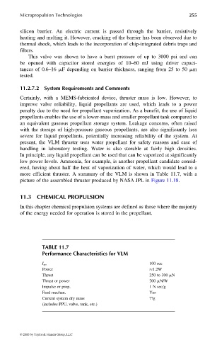
more efficient thruster. A summary of the VLM is shown in Table 11.7, with a
picture of the assembled thruster produced by NASA JPL in Figure 11.18.
11.3 CHEMICAL PROPULSION
In this chapter chemical propulsion systems are defined as those where the majority
of the energy needed for operation is stored in the propellant.
TABLE 11.7
Performance Characteristics for VLM
I sp 100 sec
Power 1.2W
Thrust 250 to 300 mN
Thrust or power 200 mN/W
Impulse or prop. 1 N sec/g
Feed mechan. Yes
Current system dry mass ??g
(includes PPU, valve, tank, etc.)
© 2006 by Taylor & Francis Group, LLC