
Page 269 - MEMS and Microstructures in Aerospace Applications
P. 269
Osiander / MEMS and microstructures in Aerospace applications DK3181_c011 Final Proof page 260 1.9.2005 12:31pm
260 MEMS and Microstructures in Aerospace Applications
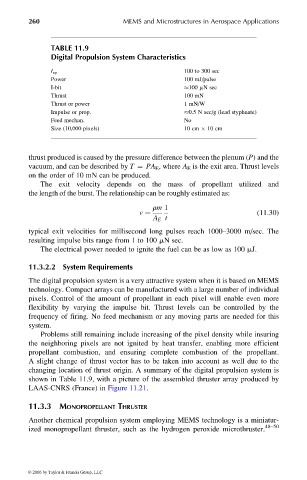
TABLE 11.9
Digital Propulsion System Characteristics
100 to 300 sec
I sp
Power 100 mJ/pulse
I-bit 100 mN sec
Thrust 100 mN
Thrust or power 1 mN/W
Impulse or prop. 0.5 N sec/g (lead styphnate)
Feed mechan. No
Size (10,000 pixels) 10 cm 10 cm
thrust produced is caused by the pressure difference between the plenum (P) and the
vacuum, and can be described by T ¼ PA E , where A E is the exit area. Thrust levels
on the order of 10 mN can be produced.
The exit velocity depends on the mass of propellant utilized and
the length of the burst. The relationship can be roughly estimated as:
rm 1
v ¼ (11:30)
A E t
typical exit velocities for millisecond long pulses reach 1000–3000 m/sec. The
resulting impulse bits range from 1 to 100 mN sec.
The electrical power needed to ignite the fuel can be as low as 100 mJ.
11.3.2.2 System Requirements
The digital propulsion system is a very attractive system when it is based on MEMS
technology. Compact arrays can be manufactured with a large number of individual
pixels. Control of the amount of propellant in each pixel will enable even more
flexibility by varying the impulse bit. Thrust levels can be controlled by the
frequency of firing. No feed mechanism or any moving parts are needed for this
system.
Problems still remaining include increasing of the pixel density while insuring
the neighboring pixels are not ignited by heat transfer, enabling more efficient
propellant combustion, and ensuring complete combustion of the propellant.
A slight change of thrust vector has to be taken into account as well due to the
changing location of thrust origin. A summary of the digital propulsion system is
shown in Table 11.9, with a picture of the assembled thruster array produced by
LAAS-CNRS (France) in Figure 11.21.
11.3.3 MONOPROPELLANT THRUSTER
Another chemical propulsion system employing MEMS technology is a miniatur-
ized monopropellant thruster, such as the hydrogen peroxide microthruster. 48–50
© 2006 by Taylor & Francis Group, LLC