
Page 270 - MEMS and Microstructures in Aerospace Applications
P. 270
Osiander / MEMS and microstructures in Aerospace applications DK3181_c011 Final Proof page 261 1.9.2005 12:31pm
Micropropulsion Technologies 261
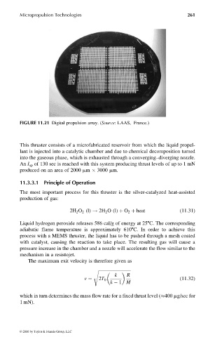
FIGURE 11.21 Digital propulsion array. (Source: LAAS, France.)
This thruster consists of a microfabricated reservoir from which the liquid propel-
lant is injected into a catalytic chamber and due to chemical decomposition turned
into the gaseous phase, which is exhausted through a converging–diverging nozzle.
An I sp of 130 sec is reached with this system producing thrust levels of up to 1 mN
produced on an area of 2000 mm 3000 mm.
11.3.3.1 Principle of Operation
The most important process for this thruster is the silver-catalyzed heat-assisted
production of gas:
2H 2 O 2 (l) ! 2H 2 O (l) þ O 2 þ heat (11:31)
Liquid hydrogen peroxide releases 586 cal/g of energy at 258C. The corresponding
adiabatic flame temperature is approximately 6108C. In order to achieve this
process with a MEMS thruster, the liquid has to be pushed through a mesh coated
with catalyst, causing the reaction to take place. The resulting gas will cause a
pressure increase in the chamber and a nozzle will accelerate the flow similar to the
mechanism in a resistojet.
The maximum exit velocity is therefore given as
s ffiffiffiffiffiffiffiffiffiffiffiffiffiffiffiffiffiffiffiffiffiffiffiffiffiffiffiffiffiffi
k R
v ¼ 2T 0 (11:32)
k 1 M
which in turn determines the mass flow rate for a fixed thrust level ( 400 mg/sec for
1 mN).
© 2006 by Taylor & Francis Group, LLC