
Page 271 - MEMS and Microstructures in Aerospace Applications
P. 271
Osiander / MEMS and microstructures in Aerospace applications DK3181_c011 Final Proof page 262 1.9.2005 12:31pm
262 MEMS and Microstructures in Aerospace Applications
Glass cover
Chamber and
catalyst
Nozzle
Propellant
Silicon inlet
component
Plenum
Tube
FIGURE 11.22 Principal setup of micro-hydrogen-peroxide thruster.
11.3.3.2 System Requirements
This thruster is the classical example of a downsized, well-proven macroscopic
propulsion system. The thruster is produced in a three-layer step as shown in Figure
11.22. The etched features of the thruster body are connected to an inlet tube for the
propellant and sealed with a Pyrex window. Great care has to be taken to ensure
good coverage of silver for the catalytic chamber.
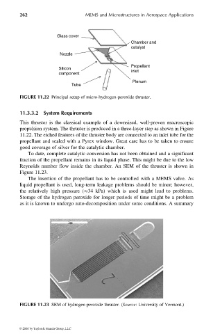
To date, complete catalytic conversion has not been obtained and a significant
fraction of the propellant remains in its liquid phase. This might be due to the low
Reynolds number flow inside the chamber. An SEM of the thruster is shown in
Figure 11.23.
The insertion of the propellant has to be controlled with a MEMS valve. As
liquid propellant is used, long-term leakage problems should be minor; however,
the relatively high pressure ( 34 kPa) which is used might lead to problems.
Storage of the hydrogen peroxide for longer periods of time might be a problem
as it is known to undergo auto-decomposition under some conditions. A summary
FIGURE 11.23 SEM of hydrogen peroxide thruster. (Source: University of Vermont.)
© 2006 by Taylor & Francis Group, LLC