
Page 320 - MEMS and Microstructures in Aerospace Applications
P. 320
Osiander / MEMS and microstructures in Aerospace applications DK3181_c014 Final Proof page 314 1.9.2005 12:47pm
314 MEMS and Microstructures in Aerospace Applications
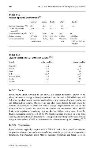
TABLE 14.2
Mission-Specific Environments 30
Mercury Venus Earth Mars Jupiter
Average temperature (8C) 350 465 15 63 144
Diurnal temperature 173 !452 0 10 !20 133 !27
range (8C)
2
Solar irradiance (W/m ) 9127 2660 1380 595 51
Surface pressure 10 9 mbar 95 bar 1013 mbar 6.1 bar 100 bar
Other considerations Vacuum H 2 SO 4 H 2 O Oxidants, Aerosols:
environment dust NH 3 ice, H 2 O ice,
NH 4 SH
TABLE 14.3
Launch Vibrations (All Entries in Grams) 31,32
Vehicle Axial Load (g) Lateral Load (g)
T34D/IUS +4.0 +5.0
Atlas-II 5.5 +1.2
Delta 6.0 3.0
H-II +5.0 +1.0
Ariane ASR44L 4.5 +0.2
Shuttle 3.5 3.4
Pegasus 13 +6
14.5.2 SHOCK
Shock differs from vibration in that shock is a single mechanical impact event
where mechanical energy is directly transferred into the device. MEMS devices will
fail when the shock event exceeds a critical stress and causes a fracture or adhesion
and delamination failures. Shock events can also cause stiction failures when the
induced displacement exceeds the critical design displacement and causes the
microstructure to touch the substrate or another microstructure. Most MEMS
devices are capable of surviving high shocks, but failures often occur from the
device packaging. Shearing off of the PC-board, package cracking, or wire bond
shearing are typical failure mechanisms. Encapsulation potting can be used to help
mitigate these effects. COTS accelerometers have been tested up to 120,000 g. 16–19
14.5.3 TEMPERATURE
Space missions typically require that a MEMS device be exposed to extreme
temperature changes. Internal stresses and many material properties are temperature-
dependent. Unfortunately most MEMS material properties are taken at room
© 2006 by Taylor & Francis Group, LLC