
Page 109 - Machinery Component Maintenance
P. 109
92 Machinery Component Maintenance and Repair
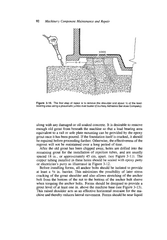
Figure 3-10. The first step of repair is to remove the shoulder and about Vz of the load-
bearing area using a pneumatic jumbo rivet buster (Courtesy Adhesive Services Company).
along with any damaged or oil soaked concrete. It is desirable to remove
enough old grout from beneath the machine so that a load bearing area
equivalent to a rail or sole plate mounting can be provided by the epoxy
grout once it has been poured. If the foundation itself is cracked, it should
be repaired before proceeding further. Otherwise, the effectiveness of the
regrout will not be maintained over a long period of time.
After the old grout has been chipped away, holes are drilled into the
remaining grout for the installation of injection tubes, and are usually
spaced 18 in., or approximately 45 cm, apart. (see Figure 3-1 1). The
copper tubing installed in these holes should be sealed with epoxy putty
or electrician’s putty as illustrated in Figure 3-12.
Before installing forms, all anchor bolts should be isolated to provide
at least a 1/4 in. barrier. This minimizes the possibility of later stress
cracking of the grout shoulder and also allows stretching of the anchor
bolt from the bottom of the nut to the bottom of the anchor bolt sleeve
when torquing the anchor bolts. Forms should be designed to provide a
grout level of at least one in. above the machine base (see Figure 3-13).
This raised shoulder acts as an effective horizontal restraint for the ma-
chine and thereby reduces lateral movement. Forms should be near liquid