
Page 113 - Machinery Component Maintenance
P. 113
% Machinery Component Maintenance and Repair
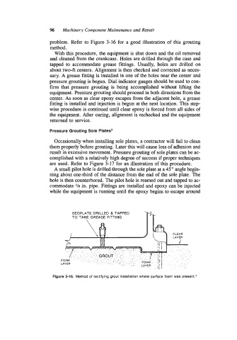
problem. Refer to Figure 3-16 for a good illustration of this grouting
method.
With this procedure, the equipment is shut down and the oil removed
and cleaned from the crankcase. Holes are drilled through the case and
tapped to accommodate grease fittings. Usually, holes are drilled on
about two-ft centers. Alignment is then checked and corrected as neces-
sary. A grease fitting is installed in one of the holes near the center and
pressure grouting is begun. Dial indicator gauges should be used to con-
firm that pressure grouting is being accomplished without lifting the
equipment. Pressure grouting should proceed in both directions from the
center. As soon as clear epoxy escapes from the adjacent hole, a grease
fitting is installed and injection is begun at the next location. This step-
wise procedure is continued until clear epoxy is forced from all sides of
the equipment. After curing, alignment is rechecked and the equipment
returned to service.
Pressure Grouting Sole Plates3
Occasionally when installing sole plates, a contractor will fail to clean
them properly before grouting. Later this will cause loss of adhesion and
result in excessive movement. Pressure grouting of sole plates can be ac-
complished with a relatively high degree of success if proper techniques
are used. Refer to Figure 3-17 for an illustration of this procedure.
A small pilot hole is drilled through the sole plate at a 45 O angle begin-
ning about one-third of the distance from the end of the sole plate. The
hole is then counterbored. The pilot hole is reamed out and tapped to ac-
commodate 118 in. pipe. Fittings are installed and epoxy can be injected
while the equipment is running until the epoxy begins to escape around
ILLED a TAPPED
ASE FITTING
Figure 3-16. Method of rectifying grout installation where surface foam was pre~ent.~