
Page 169 - Machinery Component Maintenance
P. 169
Process Machinery Piping 151
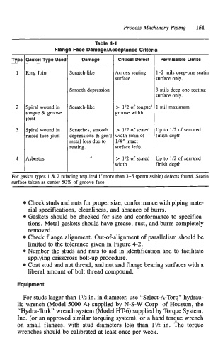
Table 4-1
- Flange Face Damage/Acceptance Criteria
Type Gasket Type Used Damage Critical Defect Permissible Limits
1 Ring Joint Scratch-like Across seating 1-2 mils deep-one seatin
surface surface only.
Smooth depression 3 mils deep-one seating
surface only.
2 Spiral wound in Scratch-like > 112 of tongue1 1 mil maximum
tongue & groove groove width
joint
3 Spiral wound in Scratches, smooth > 112 of seated Up to 112 of serrated
raised face joint depressions 8~ gen’l width (min of finish depth
metal loss due to 114 ” intact
rusting. surface left).
4 Asbestos I > 112 of seated Up to 112 of serrated
width finish depth
For gasket types 1 & 2 refacing required if more than 3-5 (permissible) defects found. Seatin
surface taken as center 50% of groove face.
Check studs and nuts for proper size, conformance with piping mate-
rial specifications, cleanliness, and absence of burrs.
Gaskets should be checked for size and conformance to specifica-
tions. Metal gaskets should have grease, rust, and burrs completely
removed.
Check flange alignment. Out-of-alignment of parallelism should be
limited to the tolerance given in Figure 4-2.
0 Number the studs and nuts to aid in identification and to facilitate
applying crisscross bolt-up procedure.
Coat stud and nut thread, and nut and flange bearing surfaces with a
liberal amount of bolt thread compound.
Equipment
For studs larger than 11/2 in. in diameter, use “Select-A-Torq” hydrau-
lic wrench (Model 5000 A) supplied by N-S-W Corp. of Houston, the
“Hydra-Tork” wrench system (Model HT-6) supplied by Torque System,
Inc. (or an approved similar torquing system), or a hand torque wrench
on small flanges, with stud diameters less than 11/2 in. The torque
wrenches should be calibrated at least once per week.