
Page 251 - Machinery Component Maintenance
P. 251
Machinery Alignment 233
Measure the Growth Using Precise Optical Instrumentation. This method
makes use of the precise tilting level and jig transit, with optical micro-
meter and various accessories. By referencing measurements to fixed el-
evations or lines of sight, movement of machine housing points can be
determined quite accurately, while the machine is running. As with the
previous method, this system is sophisticated and expensive, with deli-
cate equipment, and requires personnel more knowledgeable than the av-
erage mechanic. It is therefore reserved primarily for the more complex
machinery trains. It has given good results at times, but has also given
erroneous or questionable data in other instances. The precise tilting
level has additional use in soleplate and shaft leveling, which are not dif-
ficult to learn.
Several consultants offer optical alignment services. For the plant hav-
ing only infrequent need for such work, it is usually more practical to
engage such a consultant than to attempt it oneself.
Make Machine and/or Piping Adjustments While Running, Using Vibration
as the Primary Reference. Baumann and Tipping2 describe a number of
horizontal onstream alignments, apparently made with success. Others
are reluctant to try such adjustments for fear of movement control loss
that could lead to damage. We have, however, frequently adjusted pipe
supports and stabilizers to improve pump alignment and reduce vibration
while the pump was running.
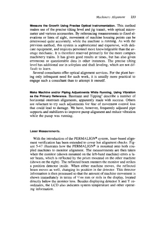
Laser Measurements.
With the introduction of the PERMALIGN@ system, laser-based align-
ment verification has been extended to cover hot alignment checks. Fig-
ure 5-47 illustrates how the PERMALIGN@ is mounted onto both cou-
pled machines to monitor alignment. The measurements are then taken
when the monitor (shown mounted on the left-hand machine) emits a la-
ser beam, which is reflected by the prism mounted on the other machine
(shown on the right). The reflected beam reenters the monitor and strikes
a position detector inside. When either machine moves, the reflected
beam moves as well, changing its position in the detector. This detector
information is then processed so that the amount of machine movement is
shown immediately in terms of Vi00 mm or mils in the display, located
directly below the monitor lens. Besides displaying detector X and Y co-
ordinates, the LCD also indicates system temperature and other operat-
ing information.