Page 247 - Machinery Component Maintenance
P. 247

Machinery Alignment   229


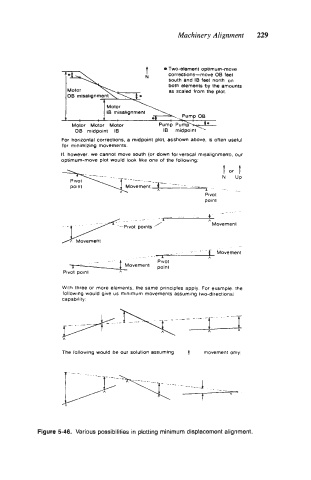
                                        t     Two-element optimum-move
                                              corrections-move  OB feet
                                              south and IB feet north  on
                                              both elements by the amounts
                                              as scaled from the plot

                              IB misalignment

                    Motor  Motor  Motor
                     OB  midpoint  IB
                  For horizontal corrections. a midpoint plot. asshown above. is often useful
                  for  minimizing movements
                 If  however  we  cannot move south (or down for vertical misalignmentl. our
                 optimum-move plot would look  like one of the following
                                                             t  or  t
                                                             N   UP
                  \Moveme;--r- point           ---   I -_  .
                    PlVOt
                                                        pivot
                                                        point
                                                             _r
                                       ..                4-
                                                         A
                  v   -  i  v   o   t  points  ;'         Movement
                    r  Movement
                                                    -    f   Movement
                                             A
                          _-               PlVOt         h
                    1'             Movement
                  Pivot point    A
                  With three or  more elements. the same  principles apply  For  example  the
                  followmg would give us minimum movements assuming two-directional
                  capability


                  The following would be our solution assuming   t   movement only:


            Figure 5-46.  Various possibilities in plotting minimum displacement alignment.
   242   243   244   245   246   247   248   249   250   251   252