
Page 242 - Machinery Component Maintenance
P. 242
224 Machinery Component Maintenance and Repair
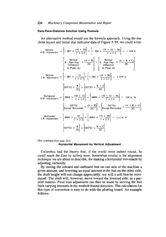
Face-Face-Distance Solution Using Formula
An alternative method would use the formula approach. Using the ma-
chine layout and initial dial indicator data of Figure 5-39, we could write:
Vertical -
O.B. Adjustment -
7 .
Vertical + B) Vertical (A + B + C)
f Face Gap X (A + f Face Gap X
Difference 2D Diffcrcncc 2D
At Plane (A) At Plane (S)
1
Vertical (10 + 56)
-.007 x A]+ 2.5 [+.,
2.5
+.03Y
2
=
X
1.R. Adjustment = 2 X x - in.
2D
Horizontal =
O.B. Adjustment
I DITTO (A + B + C) 1
2D
Horizontal =
I.B. Adjustment
2D
(Ext continued from page 221)
Horizontal Movement by Vertical Adjustment
Columbus had the theory that, if the world were indeed round, he
could reach the East by sailing west. Somewhat similar is the alignment
technique we are about to describe, for making a horizontal movement by
adjusting vertically.
By raising the inboard and outboard feet on one side of the machine a
given amount, and lowering an equal amount at the feet on the other side,
the shaft height will not change appreciably, nor will a soft foot be intro-
duced. The shaft will, however, move toward the lowered side, in a par-
allel manner. Final trim adjustment can then be made by moving the feet
back varying amounts in the nonbolt-bound direction. The calculation for
this type of correction is easy to do with the plotting board. An example
follows: