
Page 244 - Machinery Component Maintenance
P. 244
226 Machinery Component Maintenance and Repair
W 4
cc OVERLAY
PLOTTING BOARD, TURNED ON ITS SIDE
70
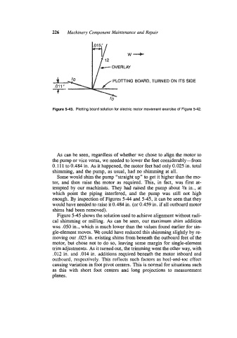
Figure 5-43. Plotting board solution for electric motor movement exercise of Figure 5-42.
As can be seen, regardless of whether we chose to align the motor to
the pump or vice versa, we needed to lower the feet considerably-from
0.11 1 to 0.484 in. As it happened, the motor feet had only 0.025 in. total
shimming, and the pump, as usual, had no shimming at all.
Some would shim the pump “straight up” to get it higher than the mo-
tor, and then raise the motor as required. This, in fact, was first at-
tempted by our machinists. They had raised the pump about 3/s in., at
which point the piping interfered, and the pump was still not high
enough. By inspection of Figures 5-44 and 5-45, it can be seen that they
would have needed to raise it 0.484 in. (or 0.459 in. if all outboard motor
shims had been removed).
Figure 5-45 shows the solution used to achieve alignment without radi-
cal shimming or milling. As can be seen, our maximum shim addition
was .050 in., which is much lower than the values found earlier for sin-
gle-element moves. We could have reduced this shimming slightly by re-
moving our .025 in. existing shims from beneath the outboard feet of the
motor, but chose not to do so, leaving some margin for single-element
trim adjustments. As it turned out, the trimming went the other way, with
.012 in. and .014 in. additions required beneath the motor inboard and
outboard, respectively. This reflects such factors as heel-and-toc effect
causing variation in foot pivot centers. This is normal for situations such
as this with short foot centers and long projections to measurement
planes.