
Page 246 - Machinery Component Maintenance
P. 246
228 Machinery Component Maintenance and Repair
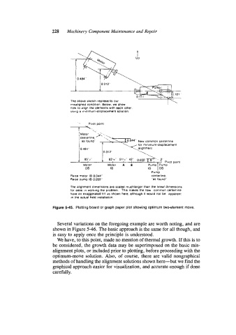
The above sketch represents our I
misaligned condition Below we show
now to ahgn the elements with each other
usmg a minimum-displacement solution
.. Pivot point
t.
..
Motor /A, '-.. ':".,
centerline.
as found" + .'.'\;"'' New common centerline
for minimum-displacement
-.
< alignment
0 484"
0.3 12" --\
L.
*
1 85'2 i 63'n 51'~ 42 0050 -@ 0
7 Pivot point
Motor Motor A 8 Pump Pump
OB IB IB OB
Pump
Raise motor 18 0.044" centerline.
Raise pump IB 0.050'' "as found"
The alignment dimensions are scaled muchlarger than the linear dimensions
for ease in working the problem This makes the new common centerline
have an exaggerated tilt as shown here, although 11 would not be apparent
in the actual field installation
Figure 5-45. Plotting board or graph paper plot showing optimum two-element move.
Several variations on the foregoing example are worth noting, and are
shown in Figure 5-46. The basic approach is the same for all though, and
is easy to apply once the principle is understood.
We have, to this point, made no mention of thermal growth. If this is to
be considered, the growth data may be superimposed on the basic mis-
alignment plots, or included prior to plotting, before proceeding with the
optimum-move solution. Also, of course, there are valid nongraphical
methods of handling the alignment solutions shown here-but we find the
graphical approach easier for visualization, and accurate enough if done
carefully.