
Page 243 - Machinery Component Maintenance
P. 243
Machinery Alignment 225
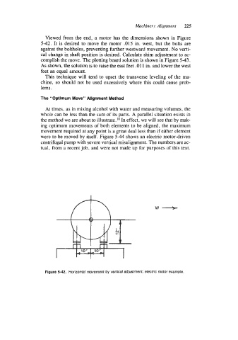
Viewed from the end, a motor has the dimensions shown in Figure
5-42. It is desired to move the motor .015 in. west, but the bolts are
against the boltholes, preventing further westward movement. No verti-
cal change in shaft position is desired. Calculate shim adjustment to ac-
complish the move. The plotting board solution is shown in Figure 5-43.
As shown, the solution is to raise the east feet .011 in. and lower the west
feet an equal amount.
This technique will tend to upset the transverse leveling of the ma-
chine, so should not be used excessively where this could cause prob-
lems.
The “Optimum Move” Alignment Method
At times, as in mixing alcohol with water and measuring volumes, the
whole can be less than the sum of its parts. A parallel situation exists in
the method we are about to illustrate.I6 In effect, we will see that by mak-
ing optimum movements of both elements to be aligned, the maximum
movement required at any point is a great deal less than if either element
were to be moved by itself. Figure 5-44 shows an electric motor-driven
centrifugal pump with severe vertical misalignment. The numbers are ac-
tual, from a recent job, and were not made up for purposes of this text.
Figure 5-42. Horizontal movement by vertical adjustment: electric motor example.