
Page 280 - Machinery Component Maintenance
P. 280
262 Machinery Component Maintenance and Repair
E PHA
GEN
I
VIBRATIO
PICKUP PICKUP
PLANE SEMAATK)N CIRCUIT
I )zL I
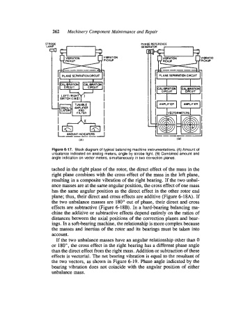
Figure 6-17. Block diagram of typical balancing machine instrumentations. (A) Amount of
unbalance indicated on analog meters, angle by strobe light. (B) Combined amount and
angle indication on vector meters, simultaneously in two correction planes.
tached in the right plane of the rotor, the direct effect of the mass in the
right plane combines with the cross effect of the mass in the left plane,
resulting in a composite vibration of the right bearing. If the two unbal-
ance masses are at the same angular position, the cross effect of one mass
has the same angular position as the direct effect in the other rotor end
plane; thus, their direct and cross effects are additive (Figure 6-18A). If
the two unbalance masses are 180" out of phase, their direct and cross
effects are subtractive (Figure 6-18B). In a hard-bearing balancing ma-
chine the additive or subtractive effects depend entirely on the ratios of
distances between the axial positions of the correction planes and bear-
ings. In a soft-bearing machine, the relationship is more complex because
the masses and inertias of the rotor and its bearings must be taken into
account.
If the two unbalance masses have an angular relationship other than 0
or 180°, the cross effect in the right bearing has a different phase angle
than the direct effect from the right mass. Addition or subtraction of these
effects is vectorial. The net bearing vibration is equal to the resultant of
the two vectors, as shown in Figure 6-19. Phase angle indicated by the
bearing vibration does not coincide with the angular position of either
unbalance mass.