
Page 281 - Machinery Component Maintenance
P. 281
Balancing of Machinery Components 263
Cross Effect of Cross Effect of
Right Unbalance Left Unbalance
1 Net Effect in Net Effect in I
L ~~,, Bearing Right Bearing J
Left
4
I 1 I
(AI STATIC UNBALANCE
Direct Effect of Direct Effect of
Left Unbalance Right Unbalance
Direct Effect of
Left Unbalance
Net Effect in Cross Effect of
Left Bearing Left Unbalance,
I
Cross Effect of Net Effect in
Right Unbalance Right Bearing
Direct Effect of
Right Unbalance
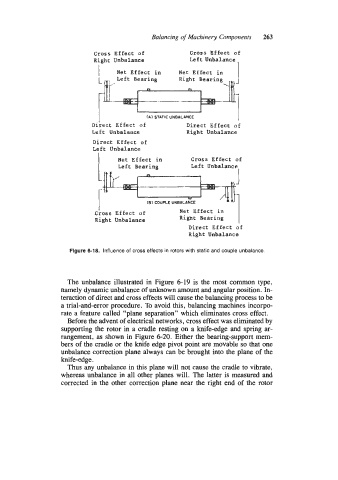
Figure 6-18. Influence of cross effects in rotors with static and couple unbalance.
The unbalance illustrated in Figure 6-19 is the most common type,
namely dynamic unbalance of unknown amount and angular position. In-
teraction of direct and cross effects will cause the balancing process to be
a trial-and-error procedure. To avoid this, balancing machines incorpo-
rate a feature called “plane separation” which eliminates cross effect.
Before the advent of electrical networks, cross effect was eliminated by
supporting the rotor in a cradle resting on a knife-edge and spring ar-
rangement, as shown in Figure 6-20. Either the bearing-support mem-
bers of the cradle or the knife edge pivot point are movable so that one
unbalance correction plane always can be brought into the plane of the
knife-edge.
Thus any unbalance in this plane will not cause the cradle to vibrate,
whereas unbalance in all other planes will. The latter is measured and
corrected in the other correction plane near the right end of the rotor