
Page 282 - Machinery Component Maintenance
P. 282
264 Machinery Component Maintenance and Repair
Cross Effect of
Left Unbalance 1
Direct Effect of Resultant Effect
Left Unbalance
I in Bearing I
Cross Effect of
Right Unbalance Direct Effect of
Resultant Effect Right Unbalance
in Bearing
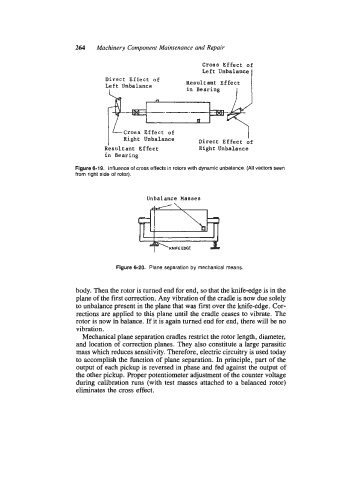
Figure 6-19. Influence of cross effects in rotors with dynamic unbalance. (All vectors seen
from right side of rotor).
Unbalance Masses
Figure 6-20. Plane separation by mechanical means.
body. Then the rotor is turned end for end, so that the knife-edge is in the
plane of the first correction. Any vibration of the cradle is now due solely
to unbalance present in the plane that was first over the knife-edge. Cor-
rections are applied to this plane until the cradle ceases to vibrate. The
rotor is now in balance. If it is again turned end for end, there will be no
vibration.
Mechanical plane separation cradles restrict the rotor length, diameter,
and location of correction planes. They also constitute a large parasitic
mass which reduces sensitivity. Therefore, electric circuitry is used today
to accomplish the function of plane separation. In principle, part of the
output of each pickup is reversed in phase and fed against the output of
the other pickup. Proper potentiometer adjustment of the counter voltage
during calibration runs (with test masses attached to a balanced rotor)
eliminates the cross effect.