
Page 188 - Macromolecular Crystallography
P. 188
HIGH-THROUGHPUT DATA COLLECTION AT SYNCHROTRONS 177
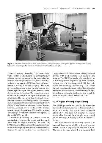
Figure 12.2 SGX-CAT data acquisition station. The CCD detector and cryogenic sample handling robot appear in the foreground. The pump
to deliver the liquid nitrogen that removes ice from the sample is located at the rear right.
Sample changing robots (Fig. 12.2) consist of two compatible with all three commercial sample chang-
parts. The first is a mechanism for moving the crys- ers and with most beamline- and facility-specific
tal from the storage dewar to the data collection systems. The SPINE protocols, which are based on
position. In most systems standard, multiaxis indus- a mounting system originated by MAR Research,
trial robots are used, the MAR CryoSample Changer include use of a two-dimensional (2D) bar code
(MARCSC) being a notable exception. The MAR within the mounting hardware (Fig. 12.3). When
device is also unique in that the samples are kept barcode readers are included within the automation
within liquid nitrogen during the transition from hardware, barcodes can be used to identify the crys-
storage to sample position. The second component tal and unambiguously link the physical sample to
of the sample changer is the liquid nitrogen storage its record in the database (see Section 12.9).
dewar itself. The capacity of this dewar determines
the maximum number of samples that can be exam-
12.3.4 Crystal mounting and positioning
ined automatically. Current capacities range from 19
(MARCSC) to 288 (Stanford Automounting System) The SPINE protocols also specify the interaction
samples. Auxiliary robots can be used to increase between the robotic hardware and the sample hard-
sample capacity. For example, SGX-CAT is currently ware. Specifically, the sample must be located
developing a system that increases the capacity of 22 mm above the base that attaches the crystal
the MAR CSC by six-fold. to the robot. Precisely how samples are mounted
Automated positioning of samples relies on on the base itself, however, is at the discretion of
compatibility between the robot and the hard- the user.
ware used for crystal mounting. In 2004, the The usual method for mounting crystals is to
SPINE(StructuralProteomicsinEurope)consortium suspend them, surrounded by a drop of cryopro-
(www.spineurope.org) established a standard spec- tectant, within a loop of nylon attached to a pin.
ification for sample holders. This specification is The pin is, in turn, attached to a magnetic base