
Page 281 - Making PIC Microcontroller Instruments and Controllers
P. 281
C
PBO,TECT
Our goal is to qeate a two-position-by-four-position intedace for the LEDS. This will
give us the equivalent of the eight buttons wo need for the operations we have ill mind.
we will use the ilterJace to control two LEDS that we will add to the LAB-X L As men-
tioned earlier. we want to be able to tum each one on and off and be able to contol the
rare at which each of the l-EDs blinlc independently.
HARDWARE I{EEDS
In order to create this eight-button interface, we need six infrared (IR) light beams, one
for each of the two rows and one each for the four columns. Each IR light bean needs
an emitler and a sensor We willalso need a simple trame lo hold lhr l2 opro-eiecronic
devices in place above the piece of paper describing the functions of the eight buttons.
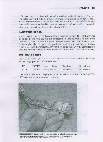
Figure 20.2 shows the scheme used by me in its initial phase with the components in
place and ready to be wired together Figure 20.3 shows the next phase in the wiring.
SOFTWARE I{EEDS
The function of the eight buttoff that the intedace will simulate will have to provide
$e following operalions for the two T tDs:
LED 1 ON/OFF Steady or blink Blink faster Blinl( slower
LED 2 ON/OFF Steady or blink Blink iaster Blint slower
Simultaneously, we will display the conditions inside the LAB-XI on the LAB-Xl's
LCD so we can actua]ly see what is going on.
wmXW Detall whing ior the touch panekloseup ol one
purposes,
side. (For our immediale exposed wiring is acleplable.)