
Page 286 - Making PIC Microcontroller Instruments and Controllers
P. 286
BUILDII{G A SIi'PLE EIGHT.EUTTOI{ TOUCH PAIIEL
THE SOFTWARE
We will divide ihc software into three independent modules:
Read $,hich oflhe eight points has been selected wilh getkey.
I Display the informalion on the LAB-XI so we can see what is going on wilh
display.
React to the selected key with do it.
Wc need to set up the scan roulinc to determine which ofthe inliared beams have
been intcnupted so we can idenlily the arca ofthe LCD that has been selected. The
scheme lbr doing so is similar to the scheme uscd in scanning a keyboard. It con_
sists ofturning on the LED for colulnn I and then cbeckjng to see ifiightbeams lbr
the column have bccn intenupted. We do this for each column one at a time. If abeam
has been interrupled, thc line associated with it will remain high.lfit has not, we go
on to the next line ard check it. We make a record of the selection if a columl1 was
We do the same thing lbr thc othcr row and then pass the intbrmation to the display
routinc. and then the executiolrouline. The execution routine uses the select case state-
nent to choose the rows and column and rcact tothem. Aftef we illle done, we resel the
row and column variables to 0 and start over,
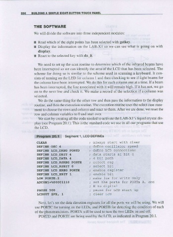
We starlby creatlng all the code needed to aclivate the LAB-Xl's liquidcrystal dis-
play (see Program 20.1). This is the standard code we use in all our programs that use
the LCD.
program 2O.1 Segment 1. LCD DEFINES
CI,EAI aLways slart {irh clear
DEFXNE OSC 4 def,ne oscilLaior speed
DEFTNE LCD DREG PORTD define LCD connecLrons
DEFTNE I,CD DBIT 4 data slarts at biL 4
DEFINE I.CD DATA 4
DEFINE LCD RSREG PORTE
DEFINE LCD_RSBIT O
DEFINE I,CD_EREG PORIE enable register
DEFINE LCD,EBIT 1
LO9,l POR[E.2 nake low for wriLe only
AtcoNl=%00001110
E to diqrital
PAUSE 5OO pause for LcD starr up
I,CDOUE $FE, 1
Ne)rt. let's set the data direction registers lbr all the ports we will be using. we wili
use PORTC tbr turning on the LEDS, and PORTB for detecting the condition of each
of the photolransistors- PORTA will be used |o 1um the two LEDS or and off.
PORTD and PORIE are being used by the LCD, as indjcated in Program 20.1.